ECE383 - Microblaze ICE 1 Part 1
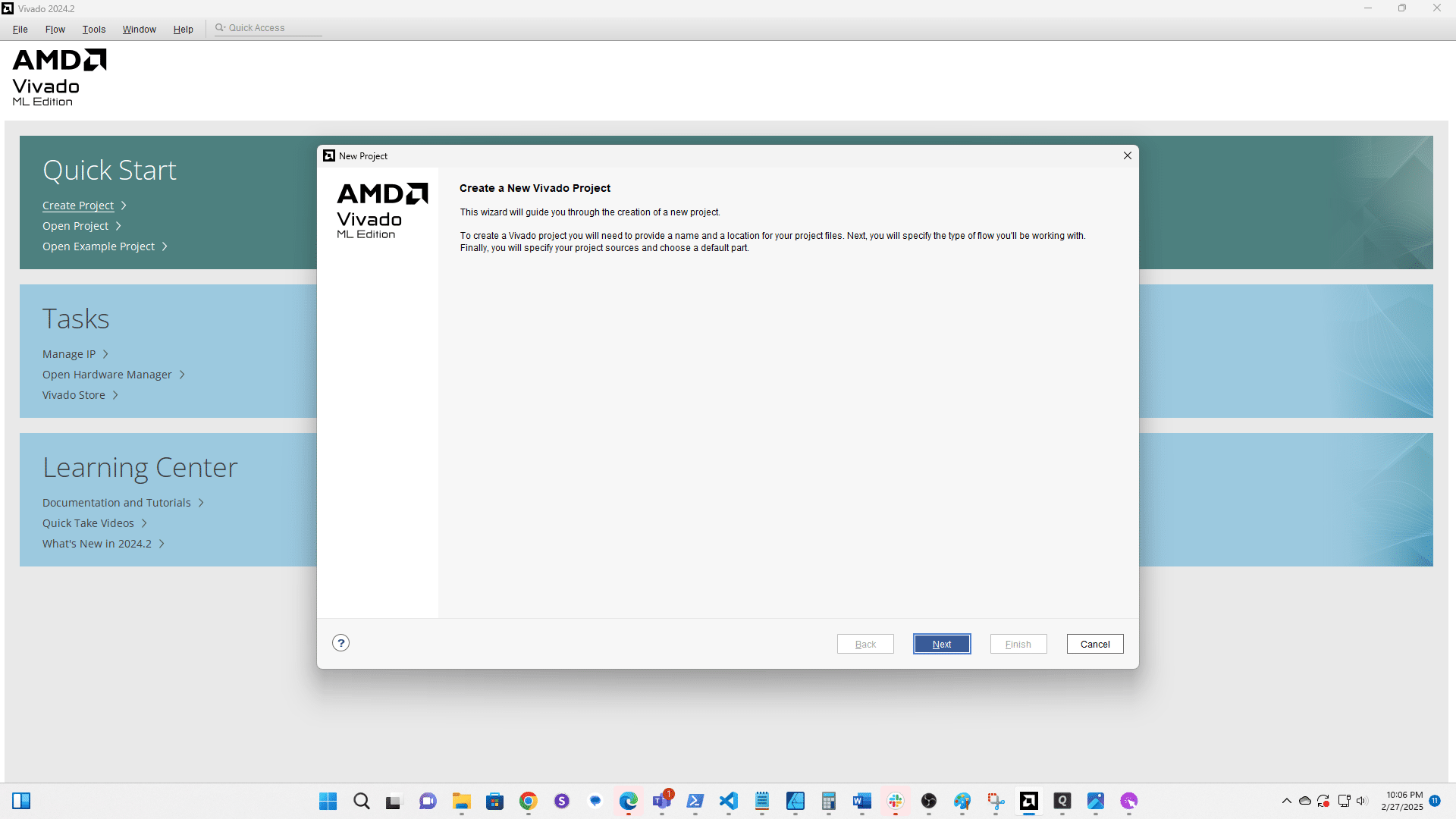
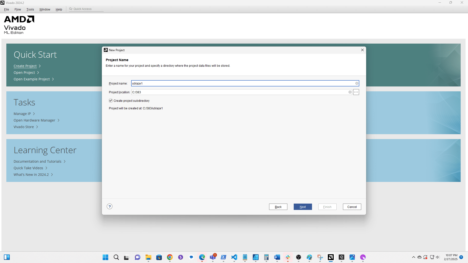
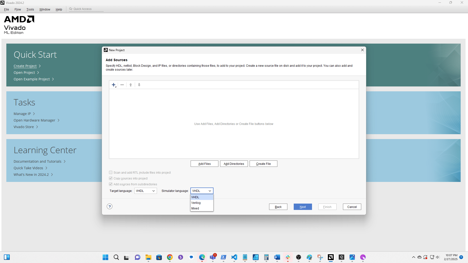
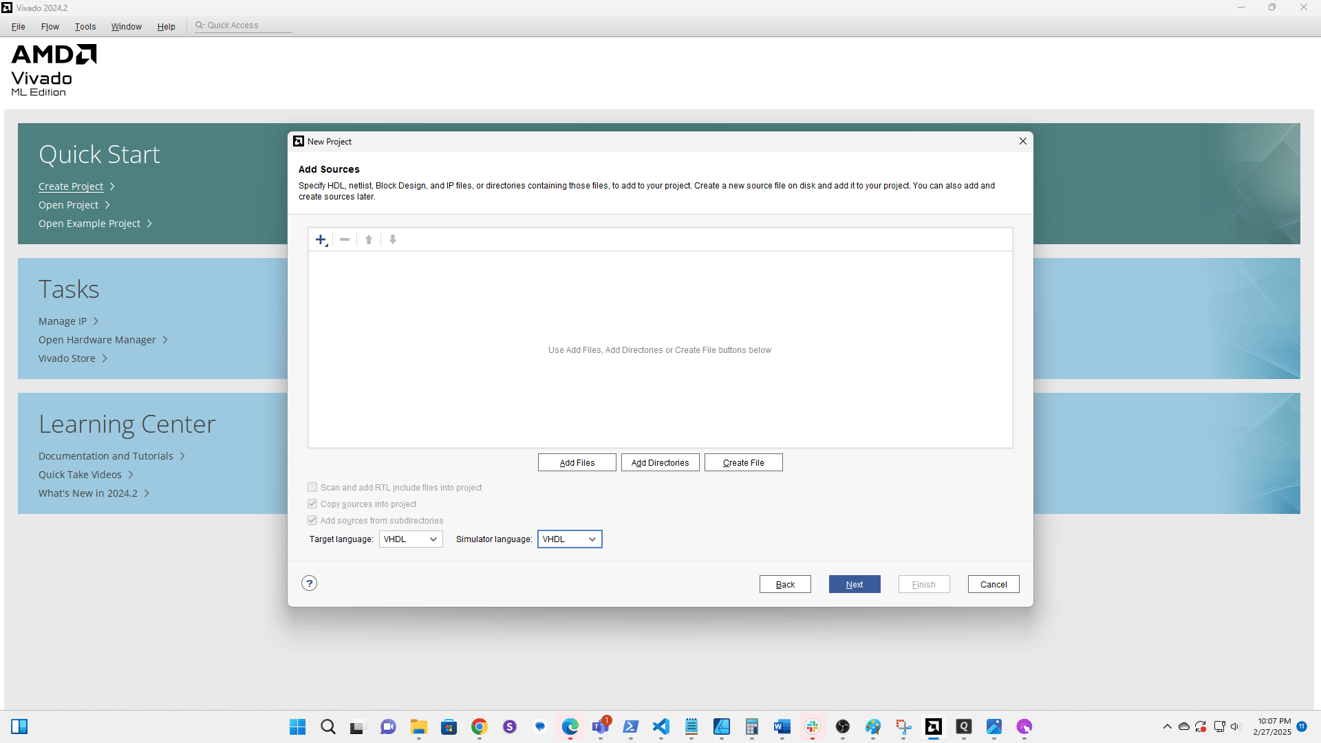
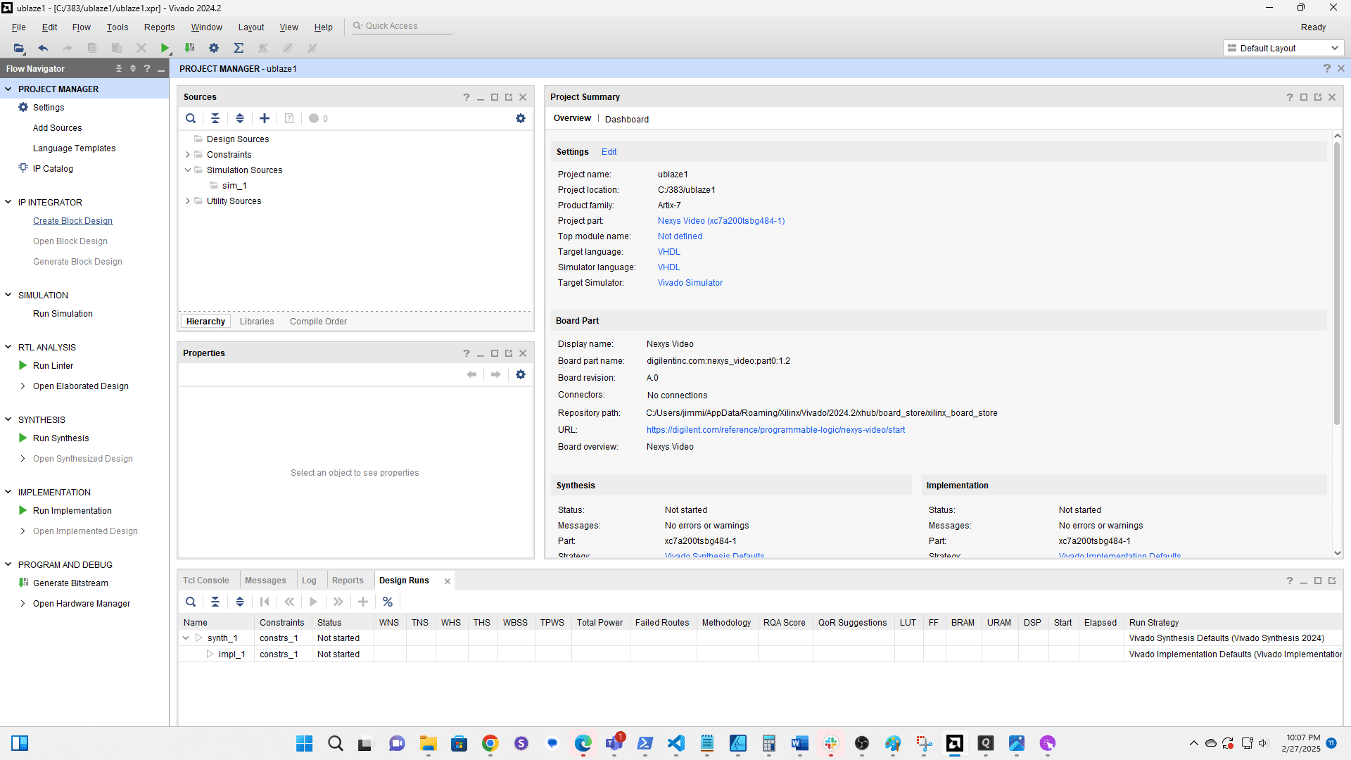
Create a New Project
Click here
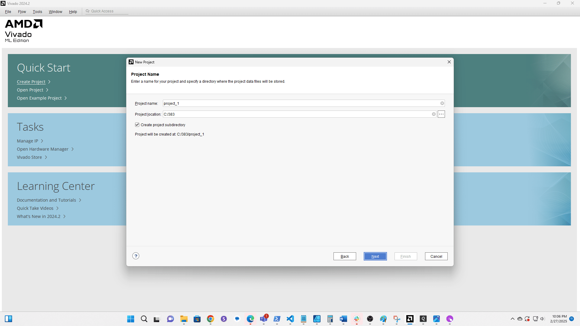
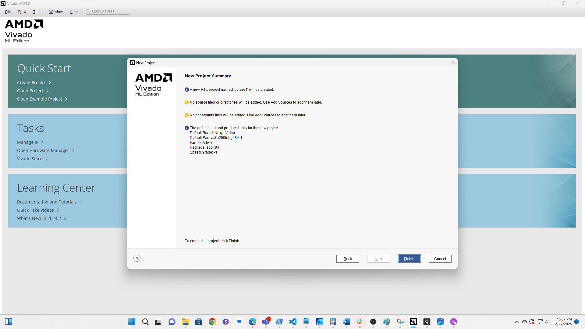
Rename your project.
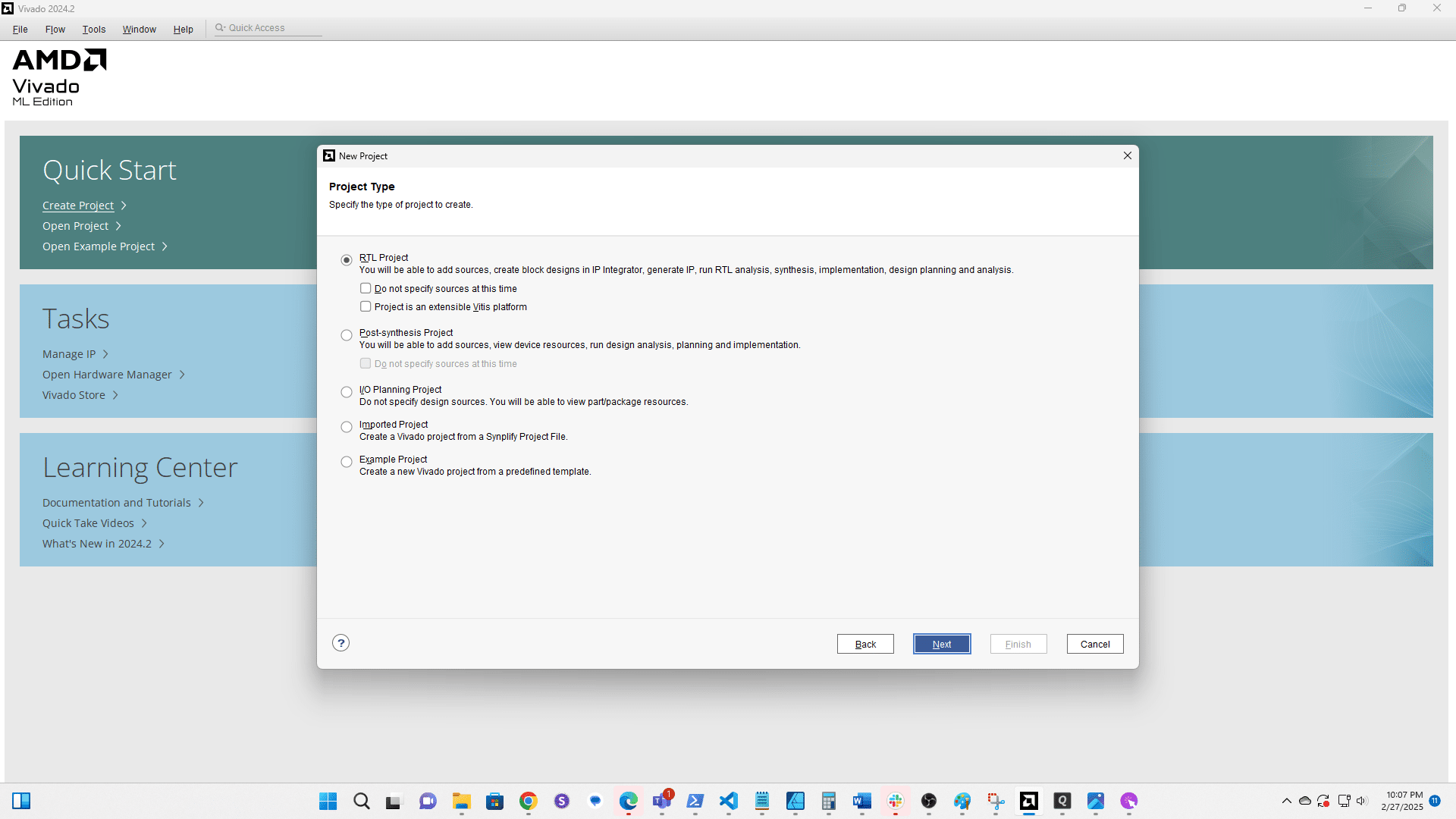
Click here
Click here
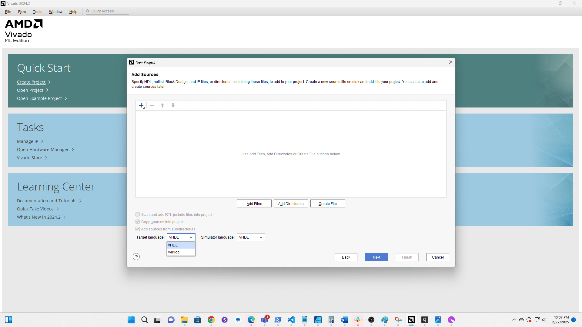
Click here

Click here
Click here
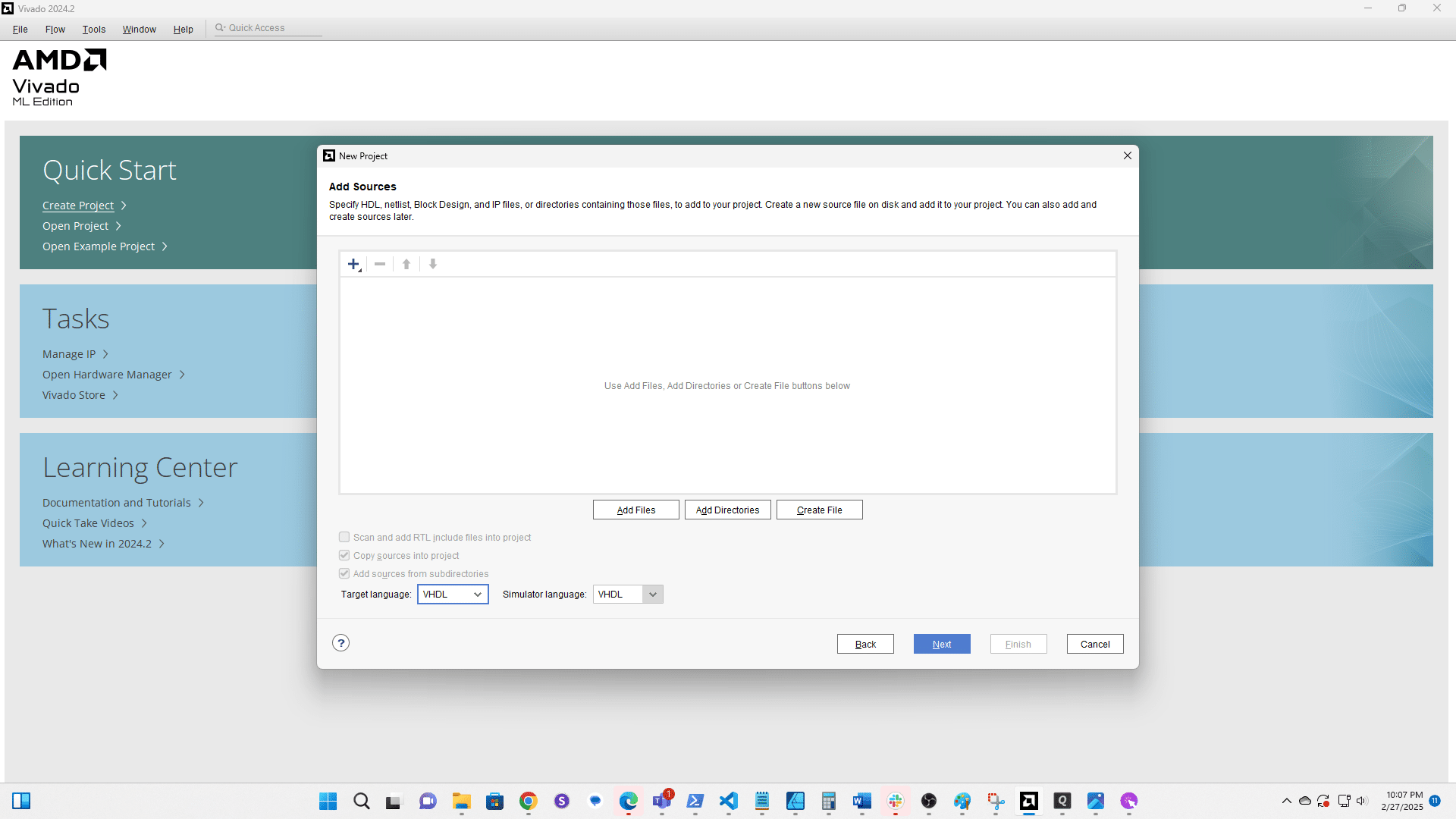
Click here
Click here
Click here
Click here
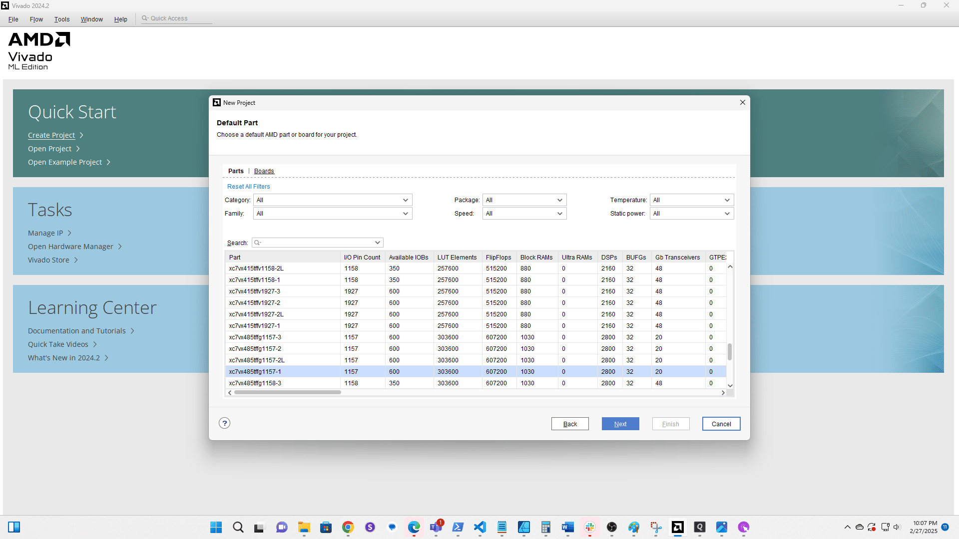
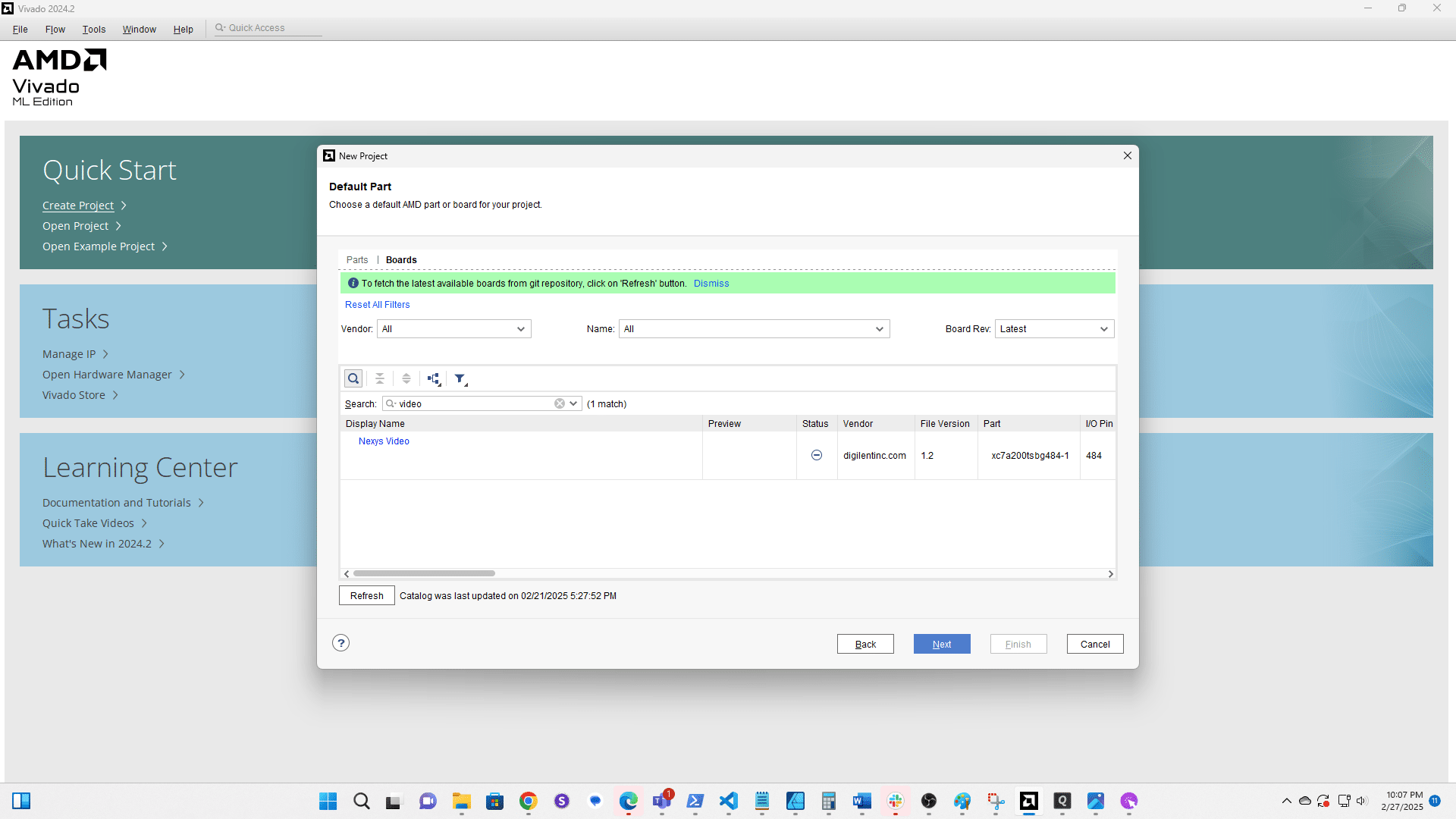
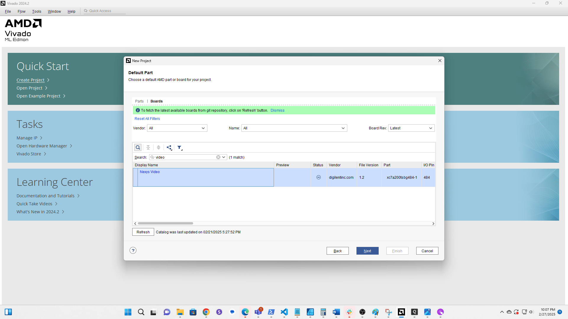
Search for "video"
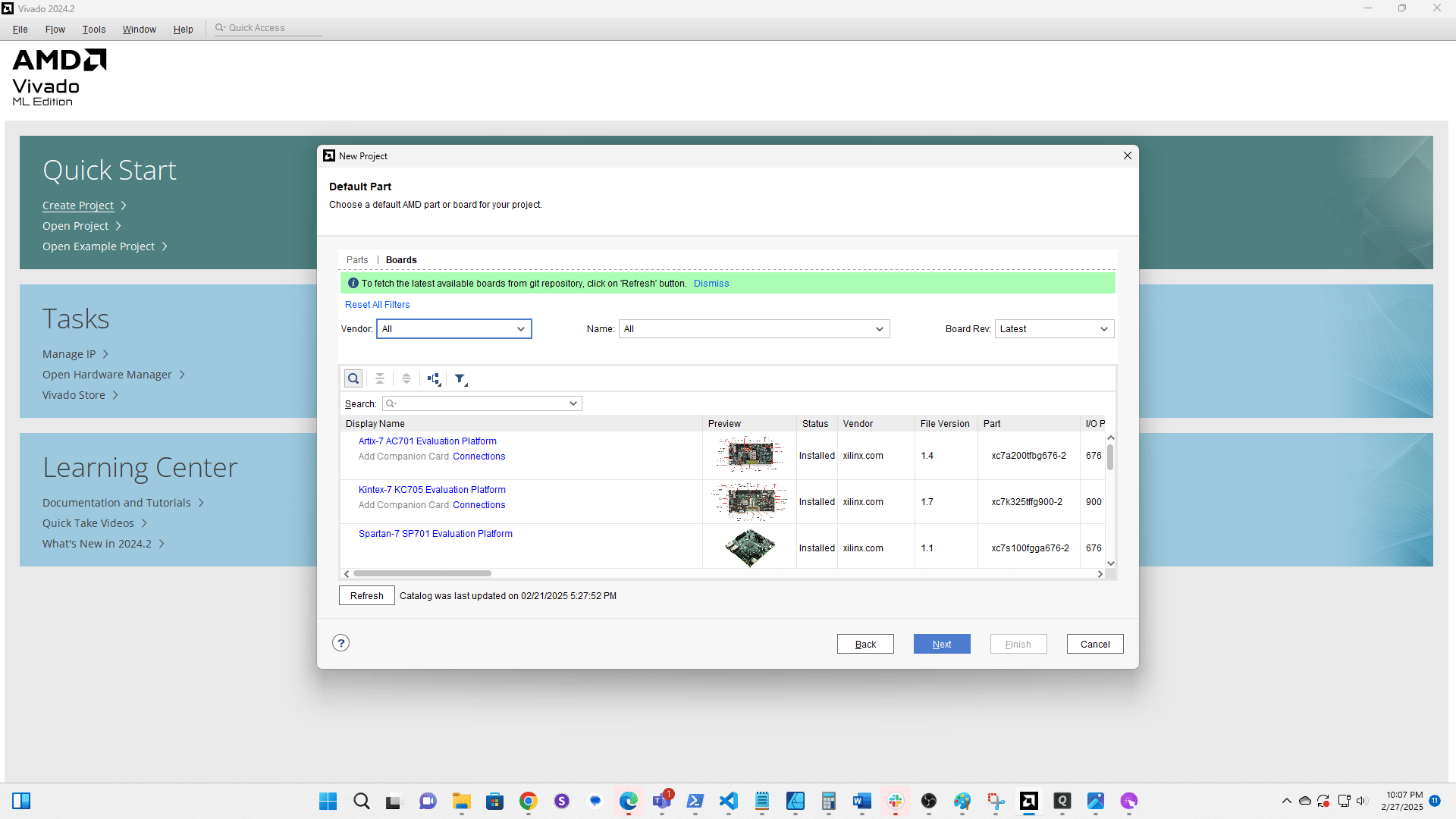
Select the Nexys Video
Click here
Click here
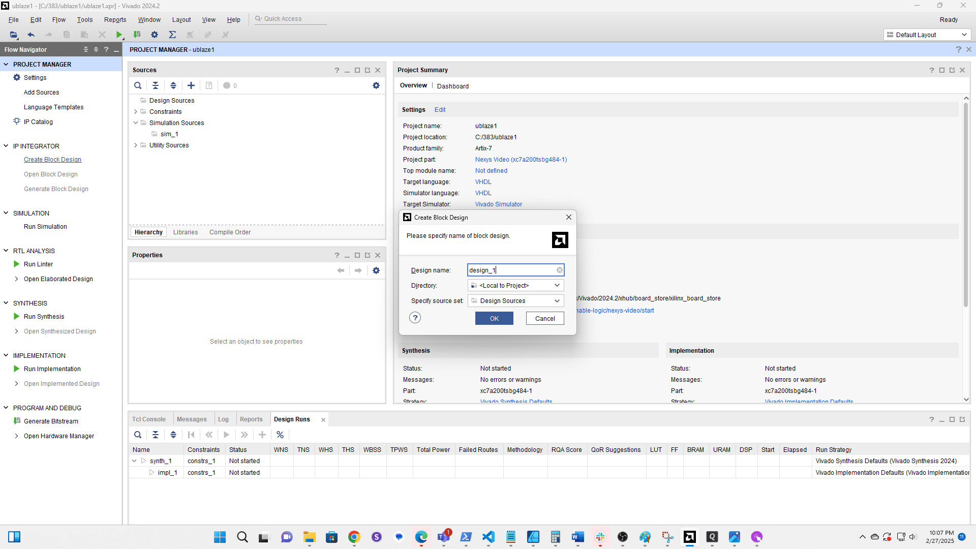
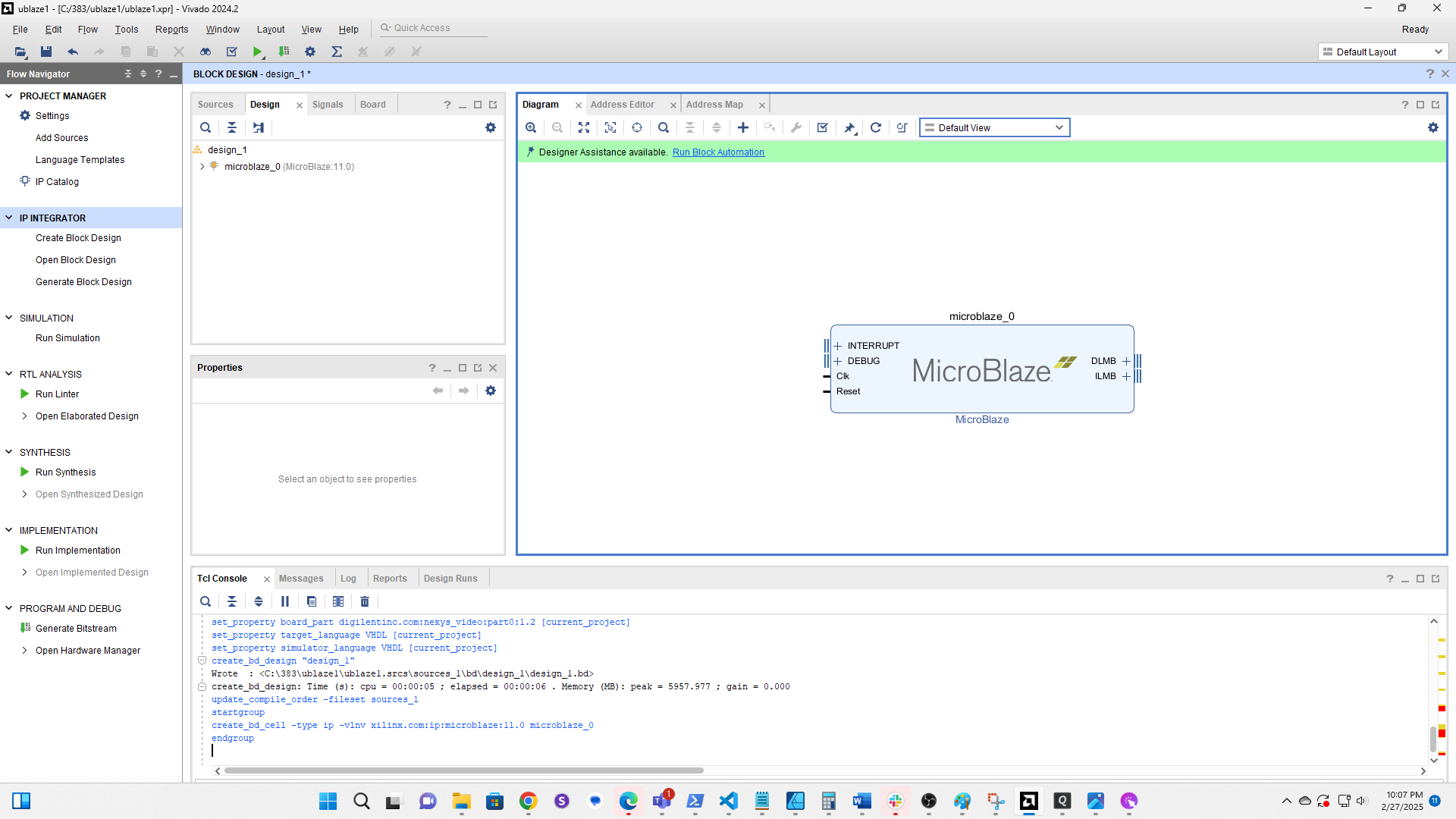
Click Create Block Design
Accept the default name
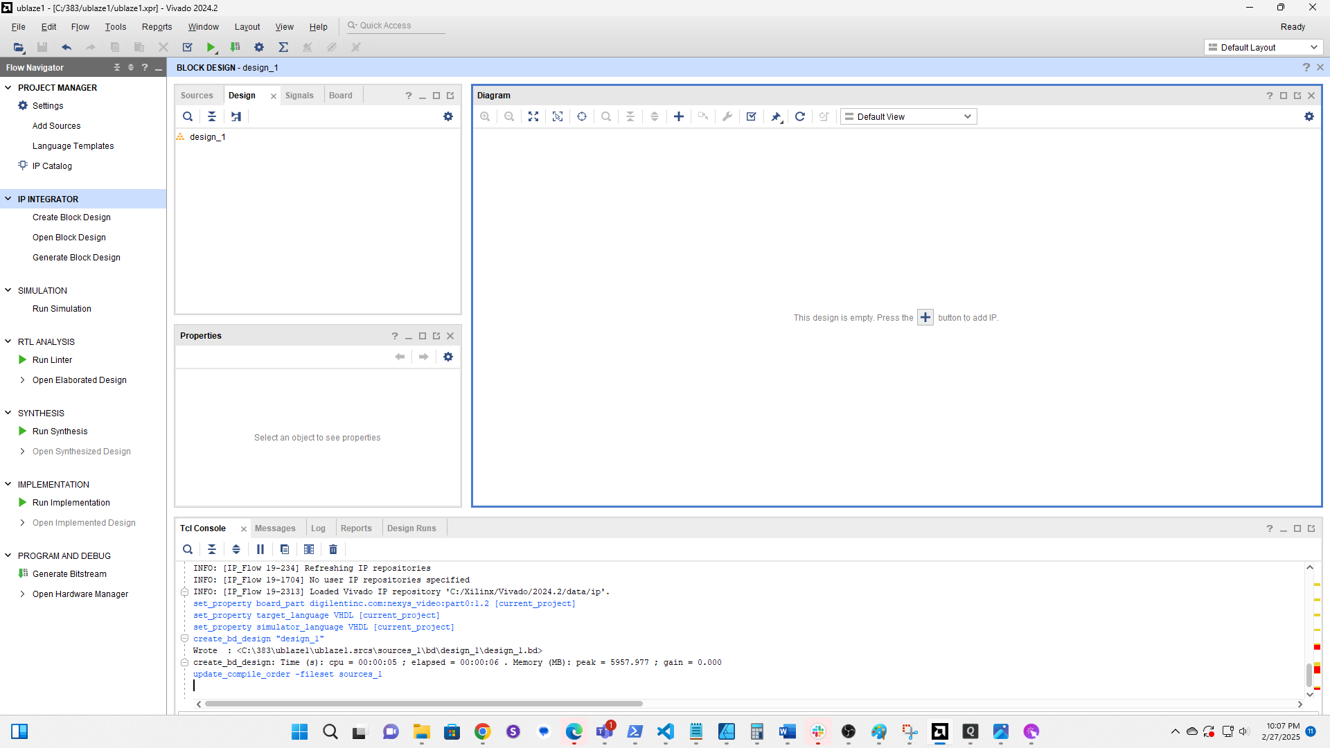
Click the plus to add a component
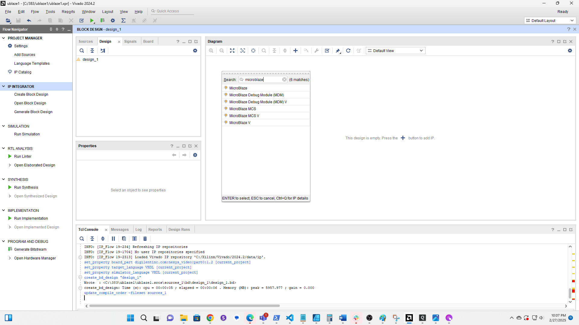
Search for Microblaze and double click it
Click Run Block Automation
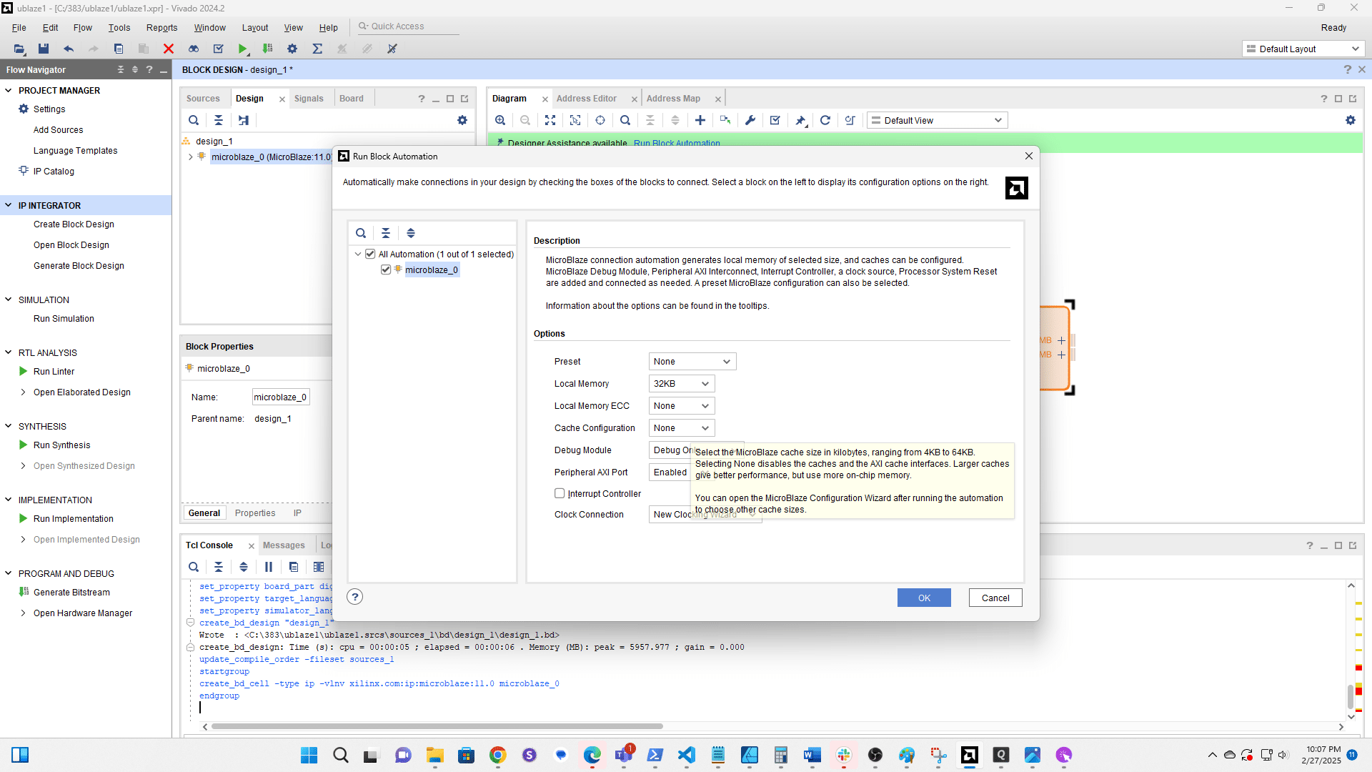
Change Local Memory to 32KB
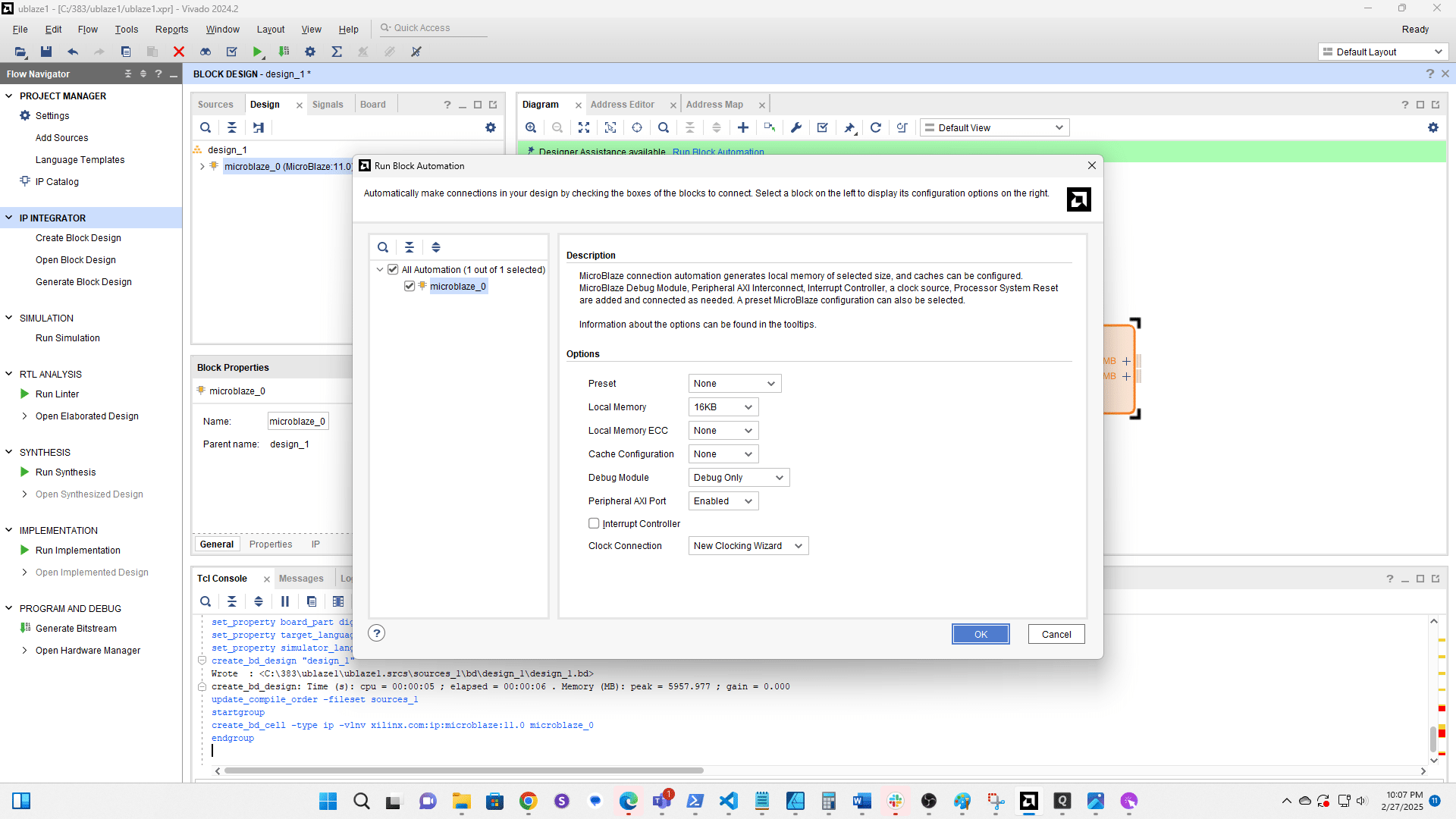
Change Cache Configuration to 16KB
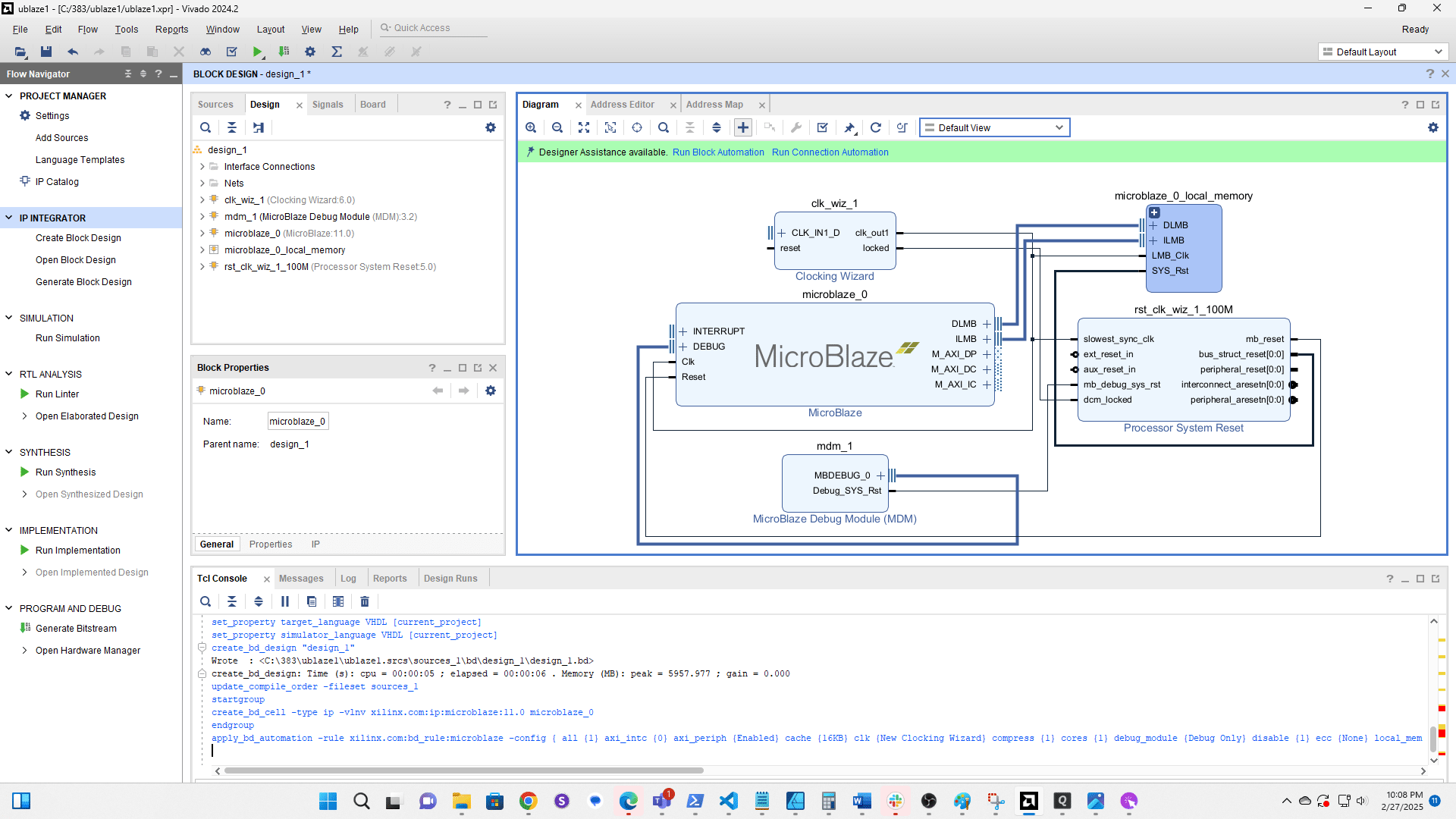
Click OK

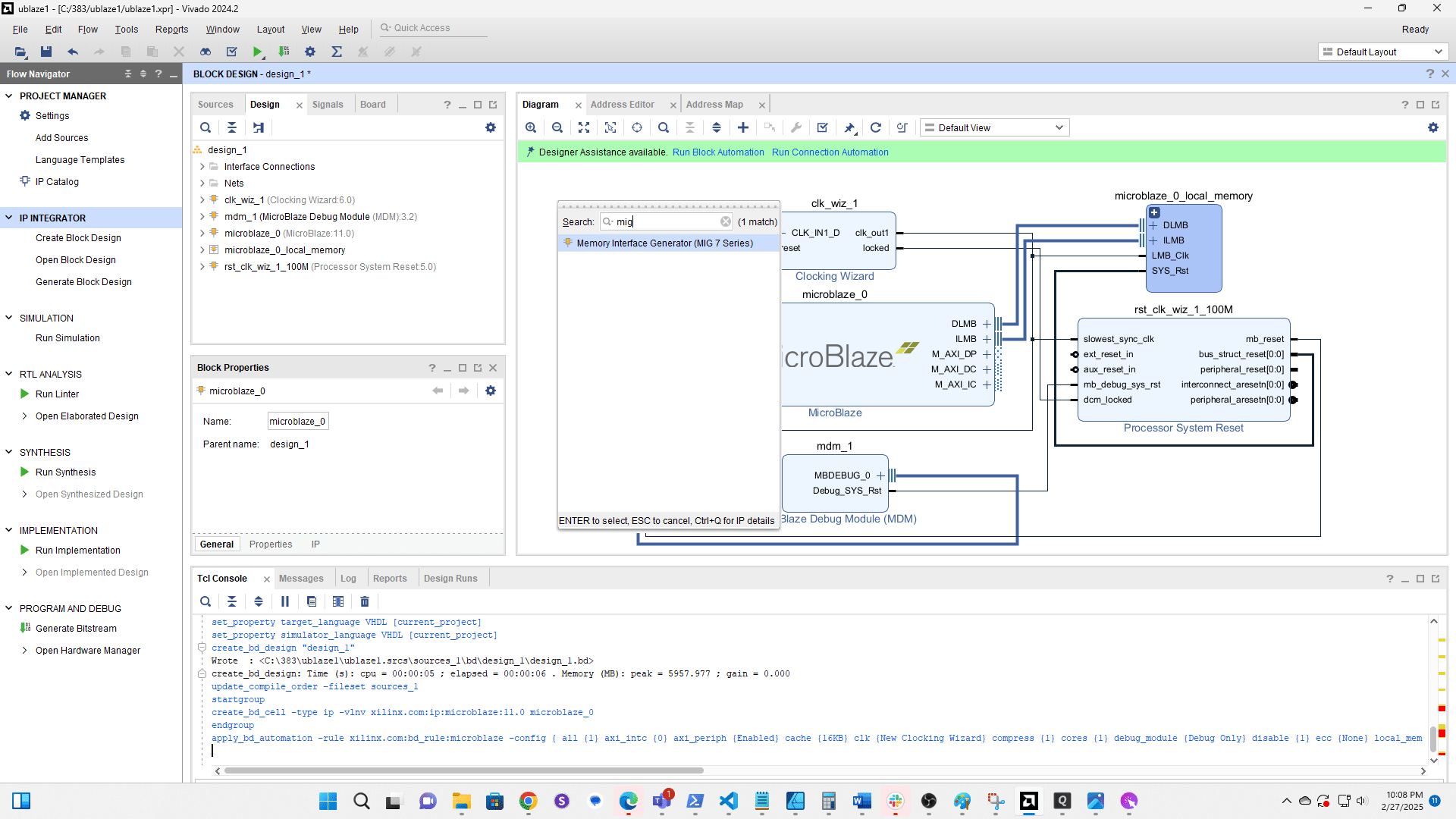
Click + to add a new component
Search for MIG

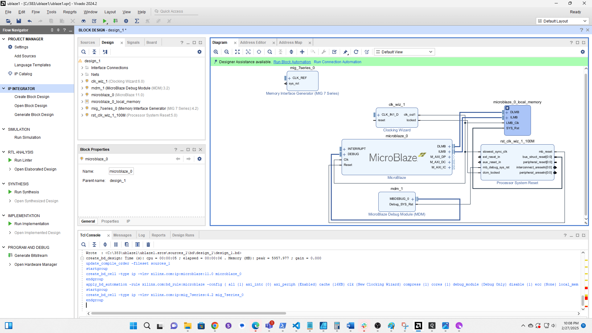
Double click to add Memory Intergace Generator (MIG)
Click Run Block Automation
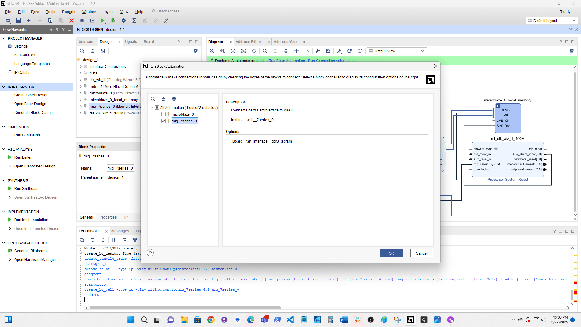
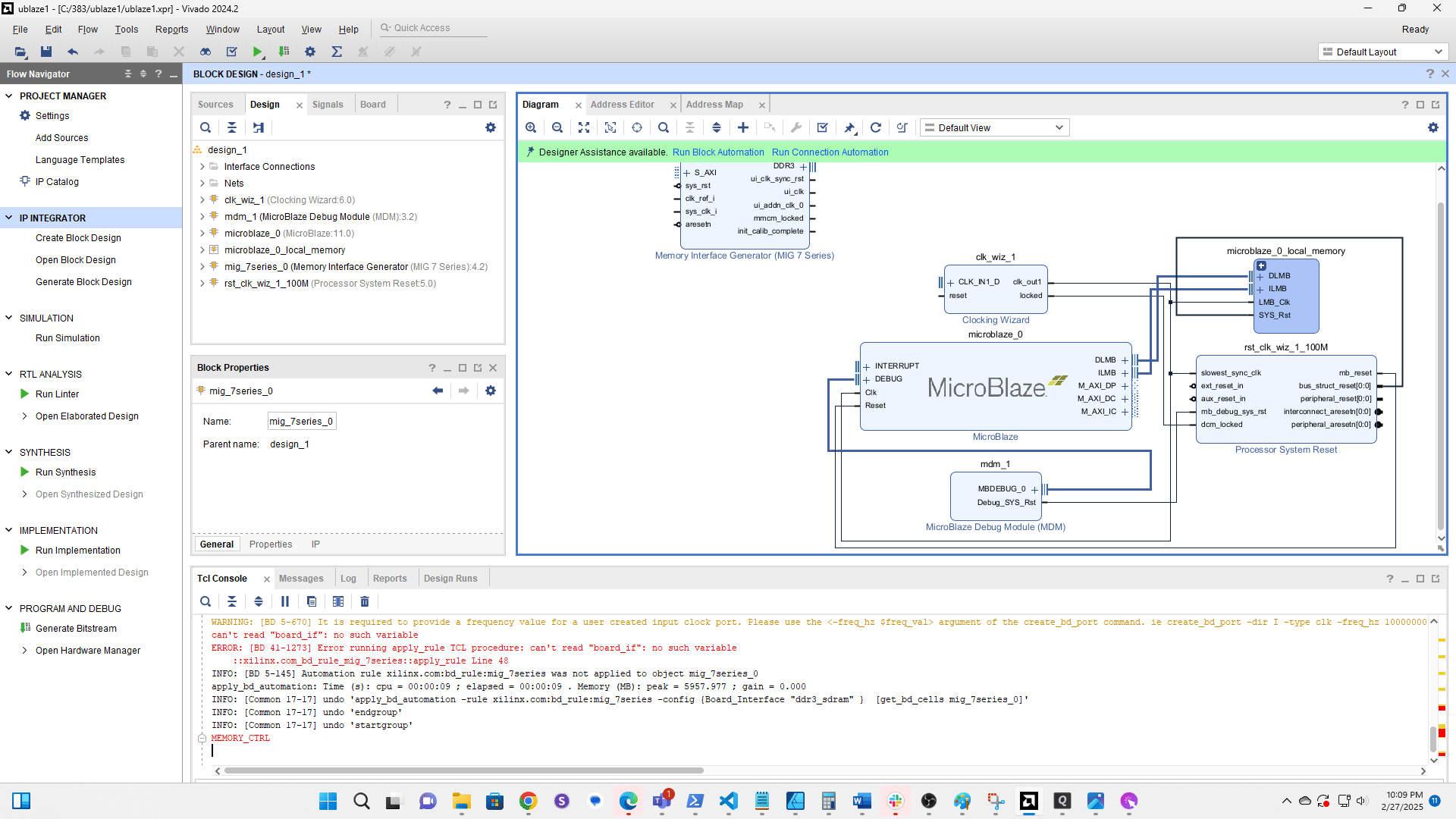
Select mig 7series 0
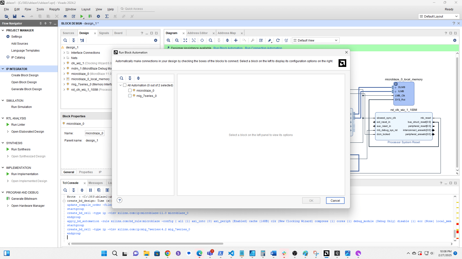
Click here
Error [BD 41-1273] is expected and is OK.
![Error [BD 41-1273] is expected and is OK.](https://assets.guidejar.com/uploads/bbe34535-a15e-40f9-a605-2fbcf9e5a050/EEETTDLl5bSGK1be8wWFsic8V683/1cfacf65-e02a-409b-a54c-f403cc525227/1740719349864.png)
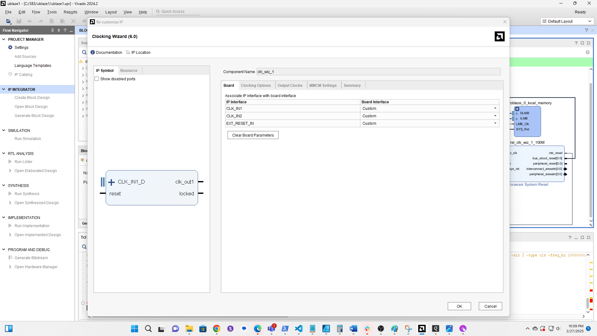
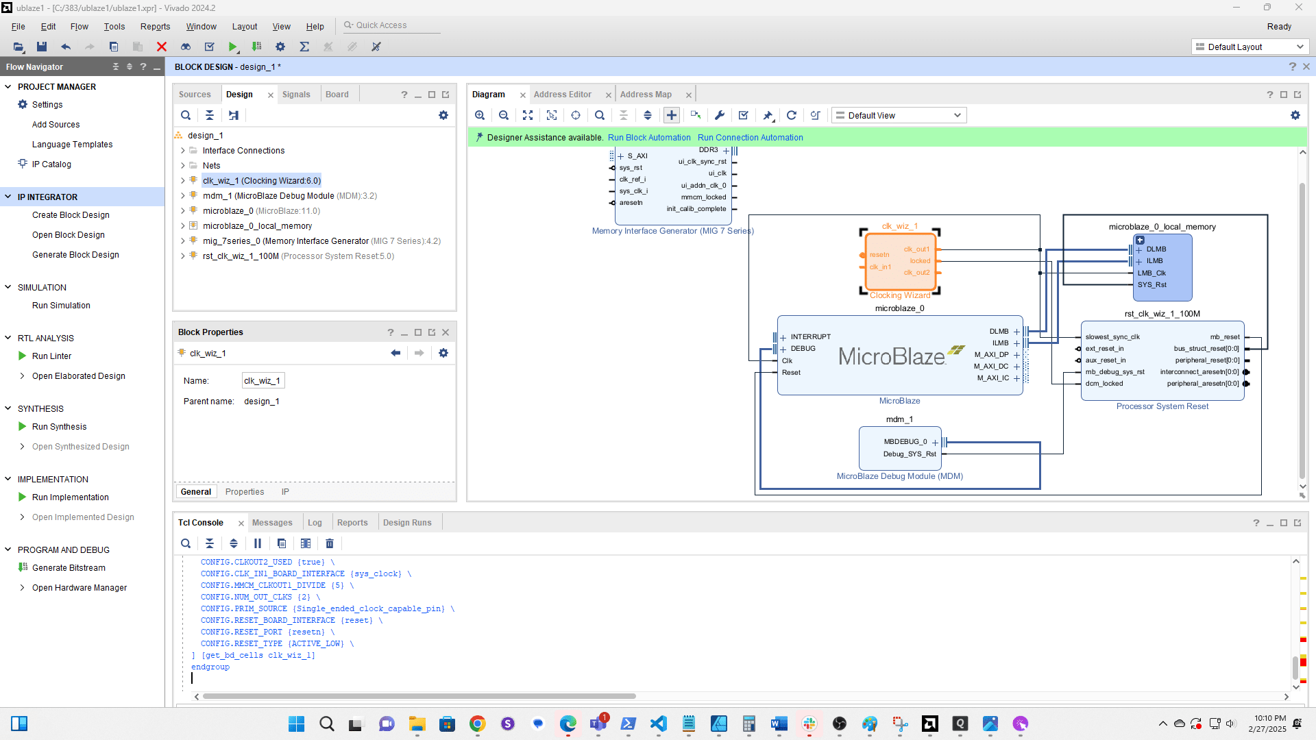
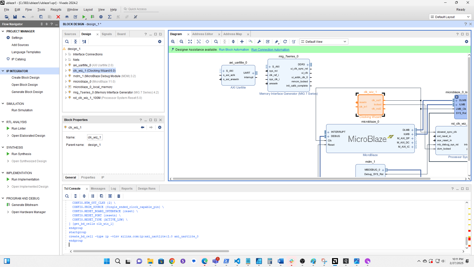
Double click the Clock Wiz component
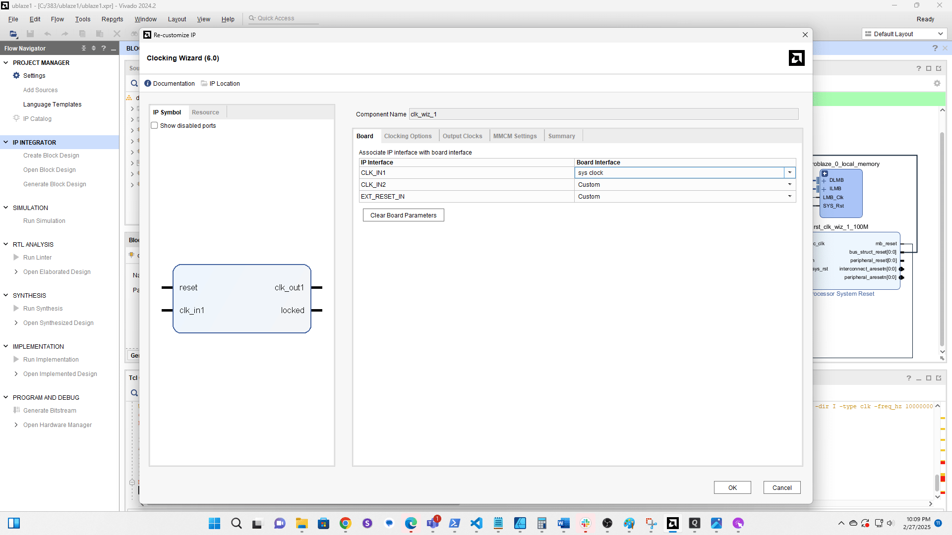
Set CLK_IN1 to sys clock
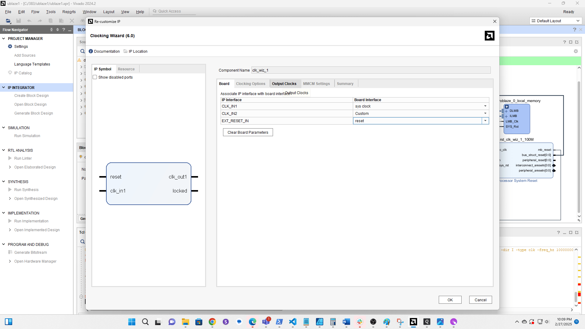
Set EXT RESET IN to reset
Click here
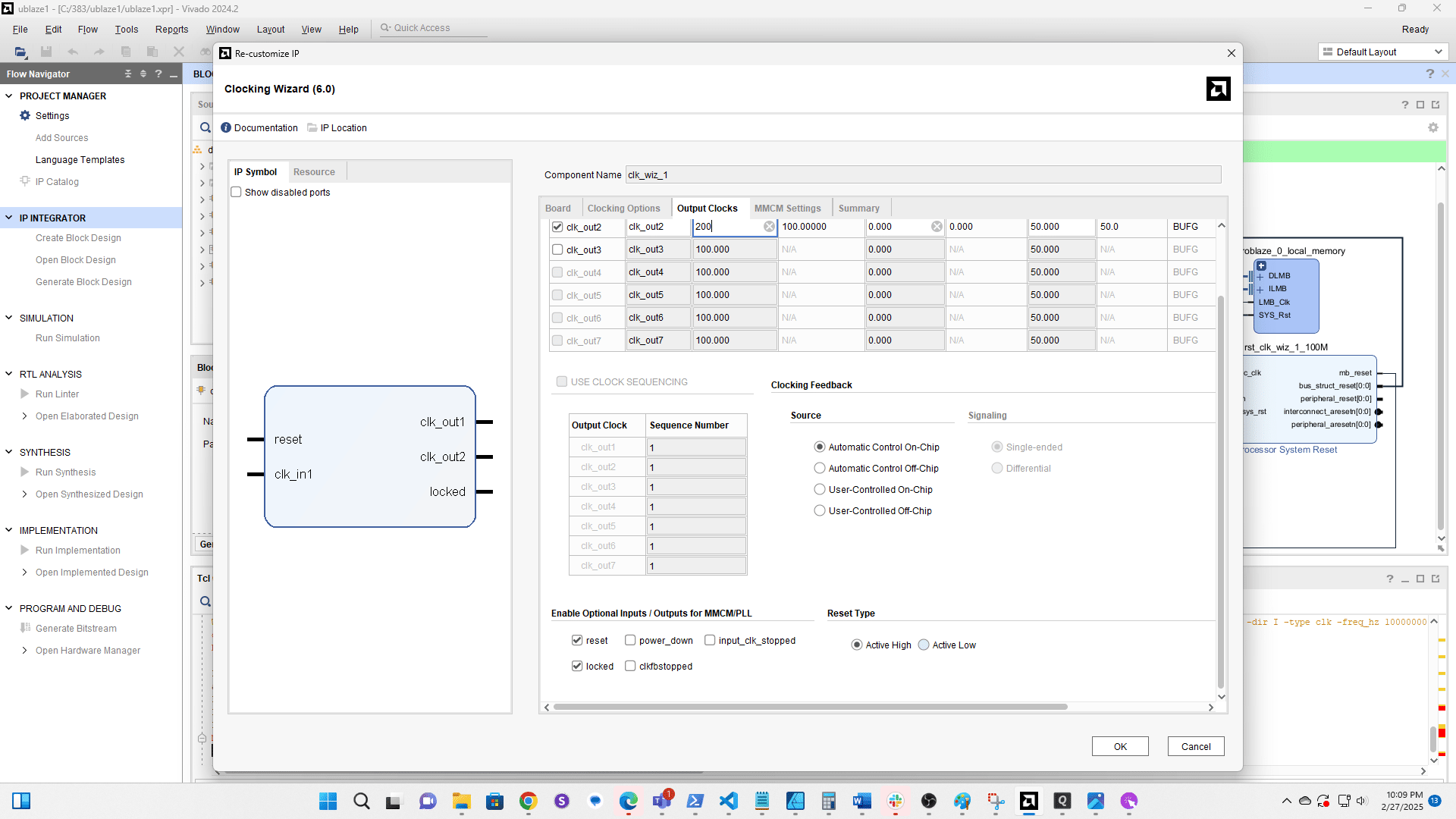
Enable clk out2
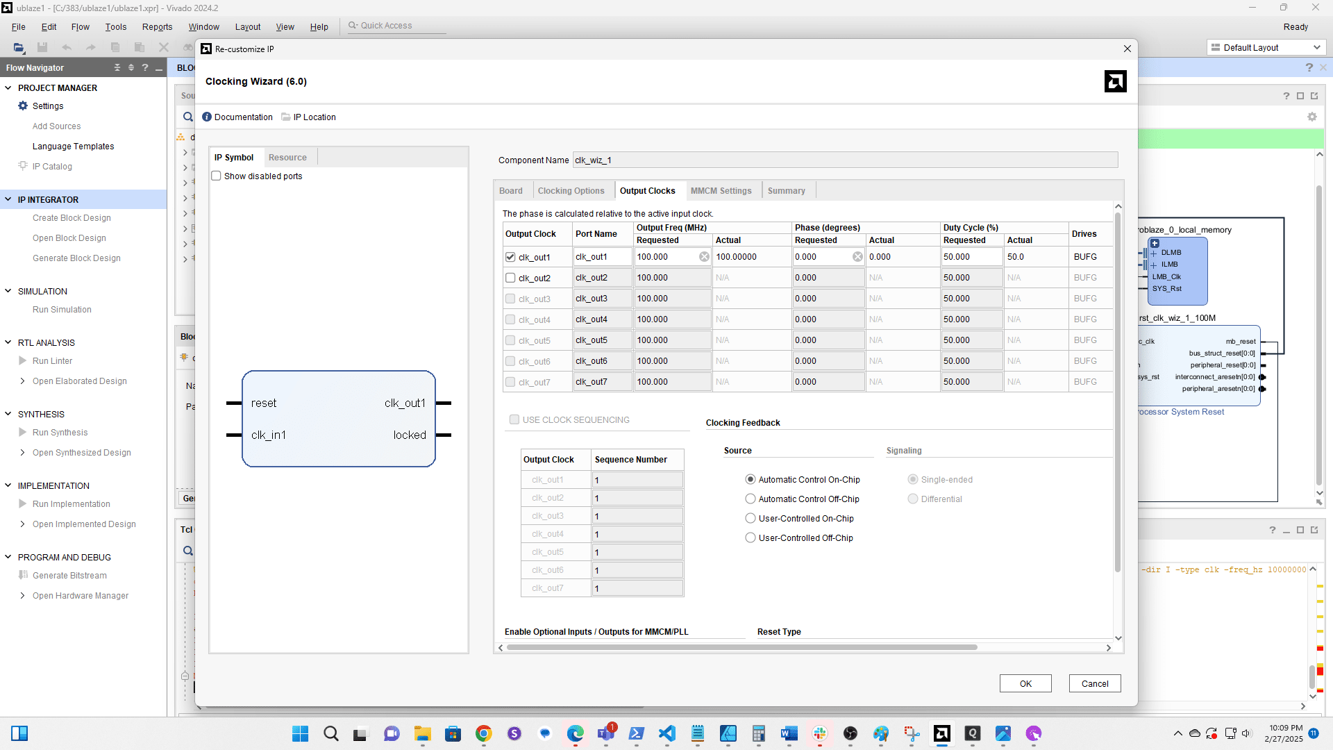
Set the frequency to 200MHz

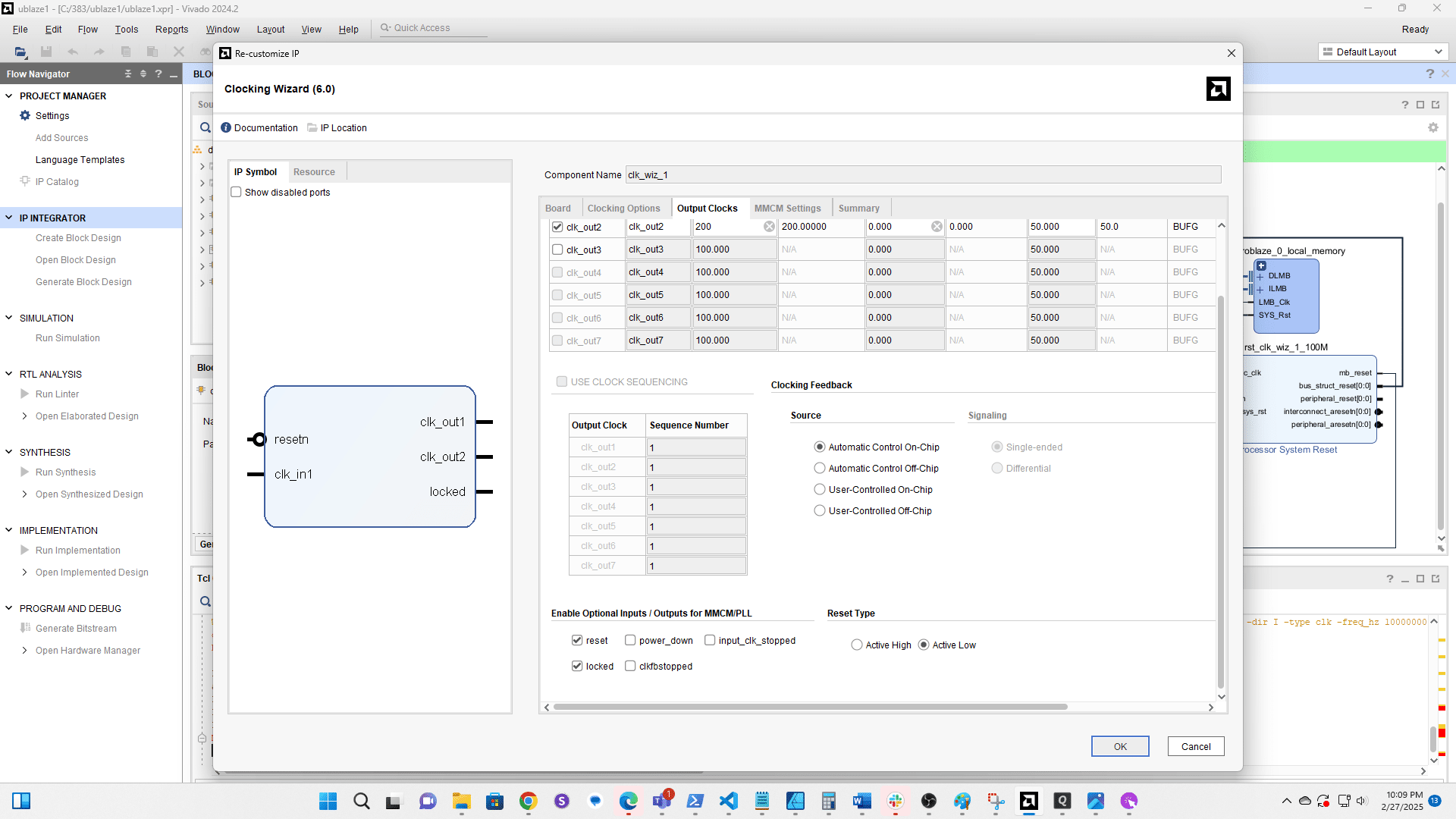
Set the Reset Type to Active Low
Click here
Click + to add a new component
Search for and add AXI Uartlite

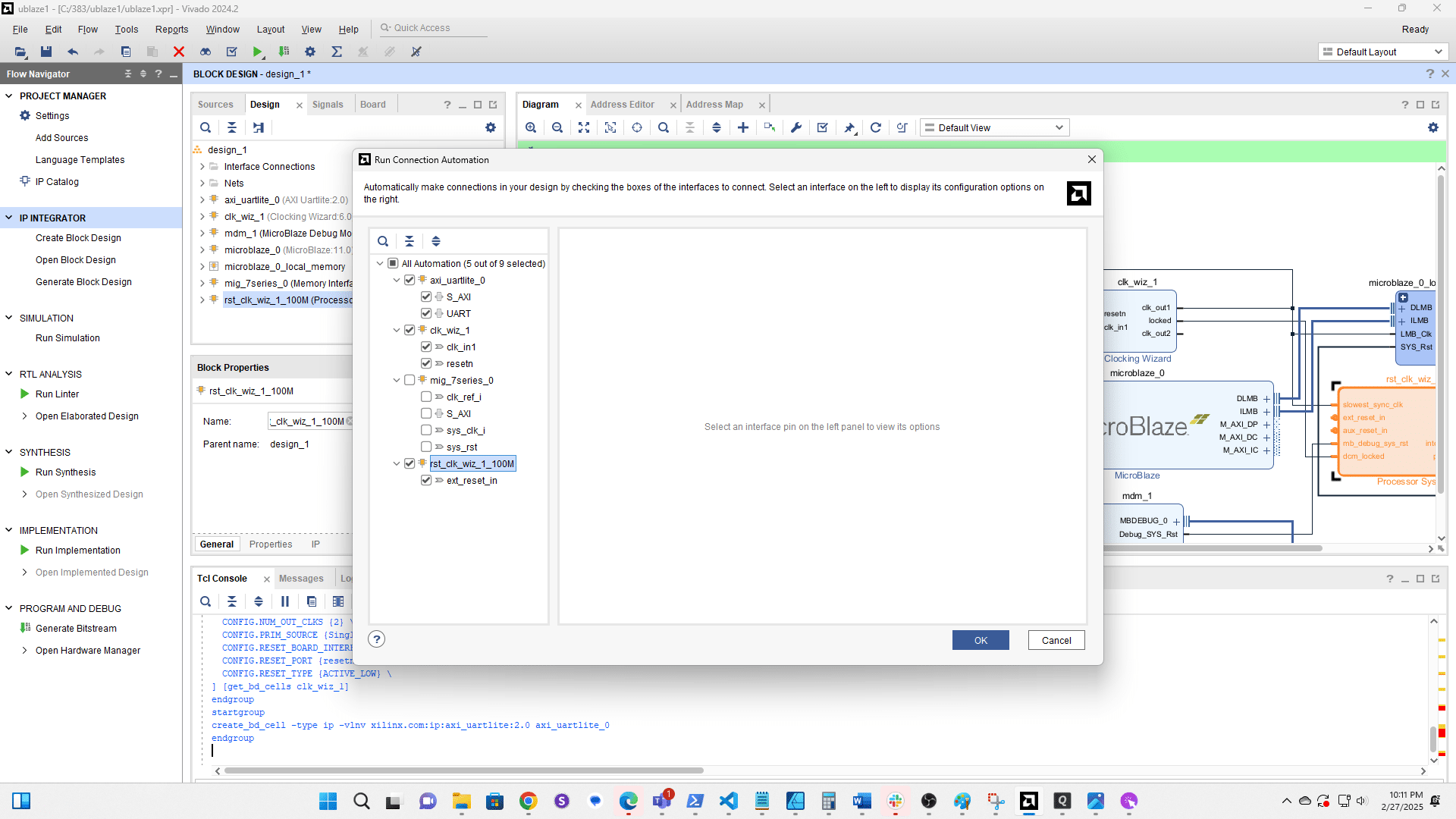
Run Connection Automation
Select all components except the MIG and Microblaze (if visible)
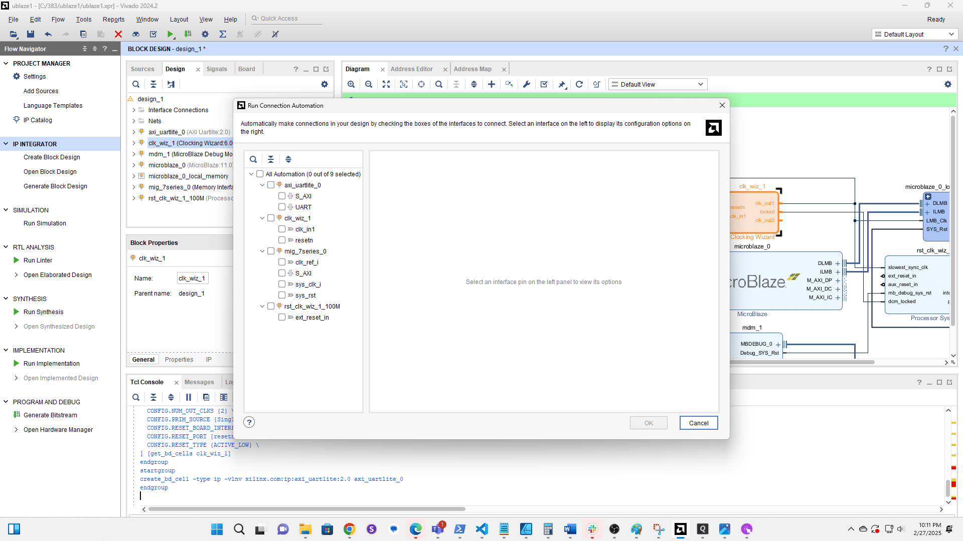
Click here
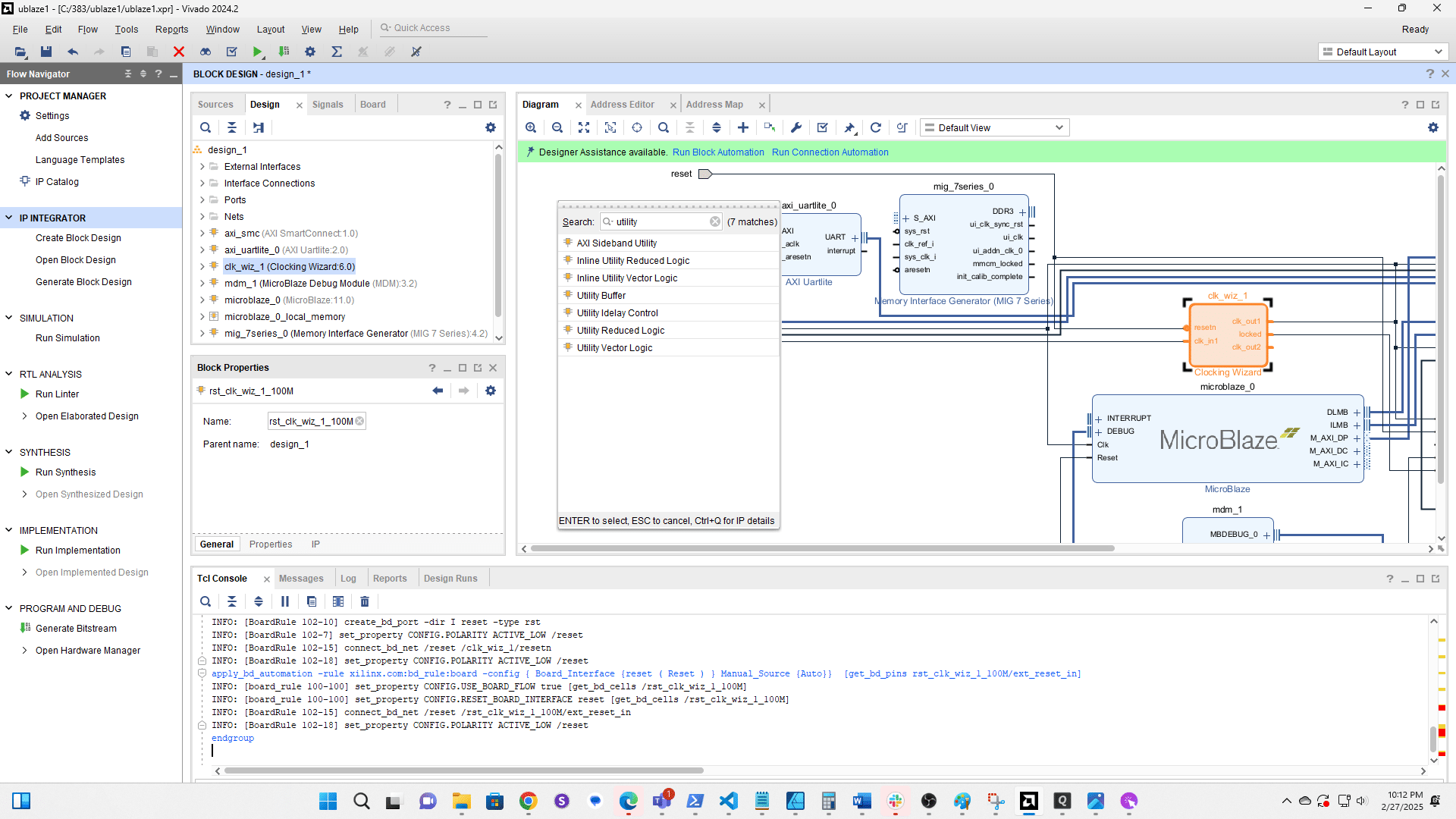
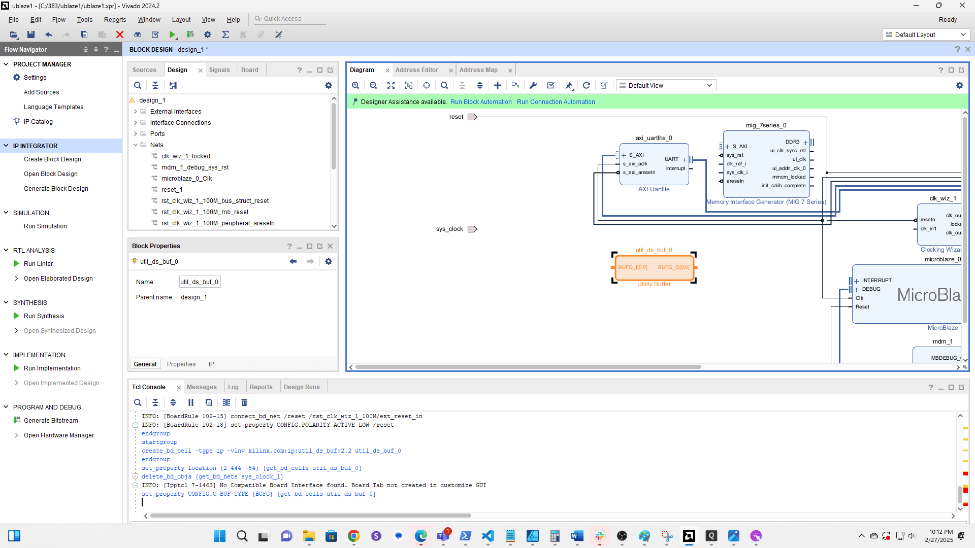
Click the + to add a new component
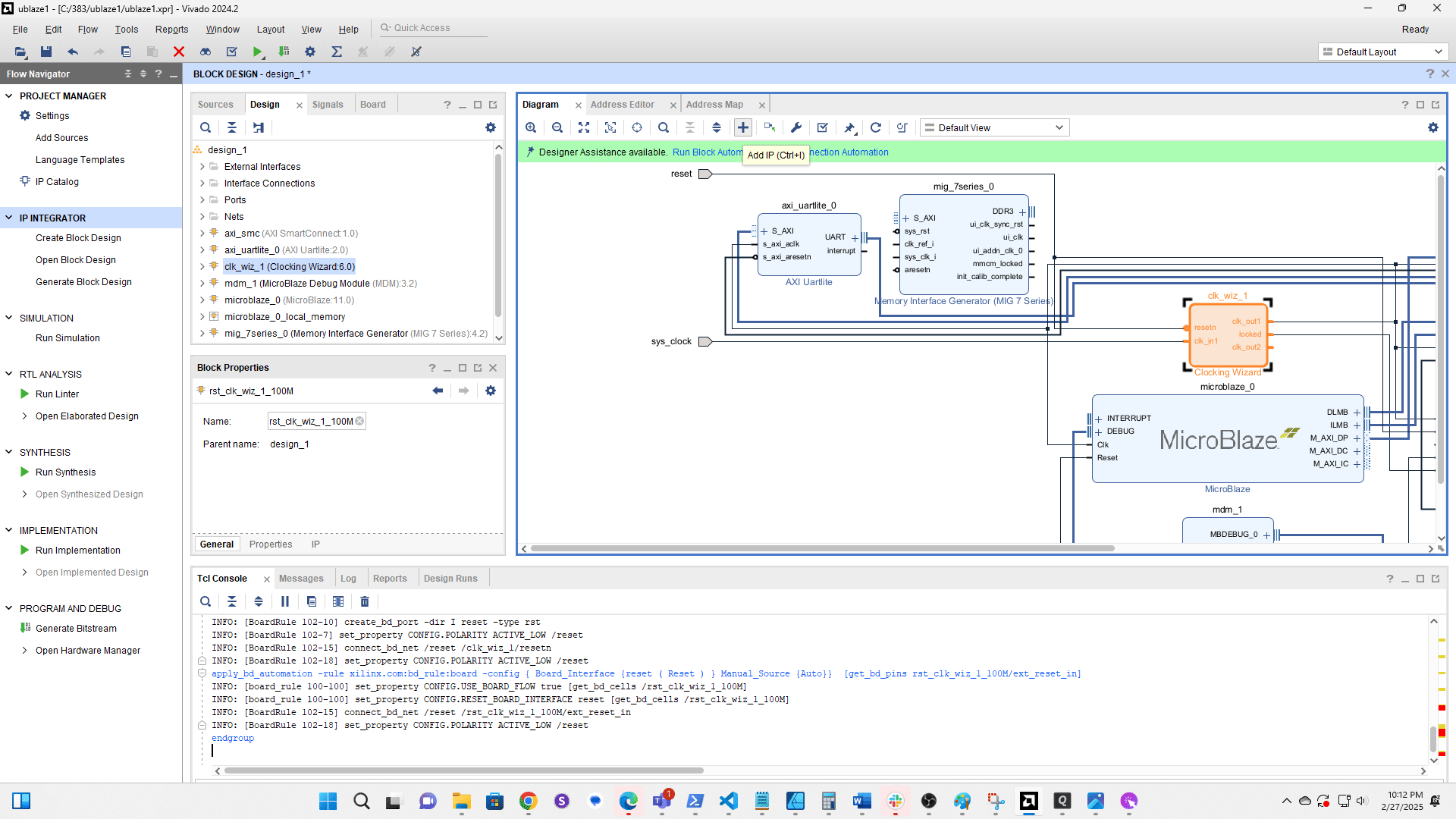
Search for and add the Utility Buffer
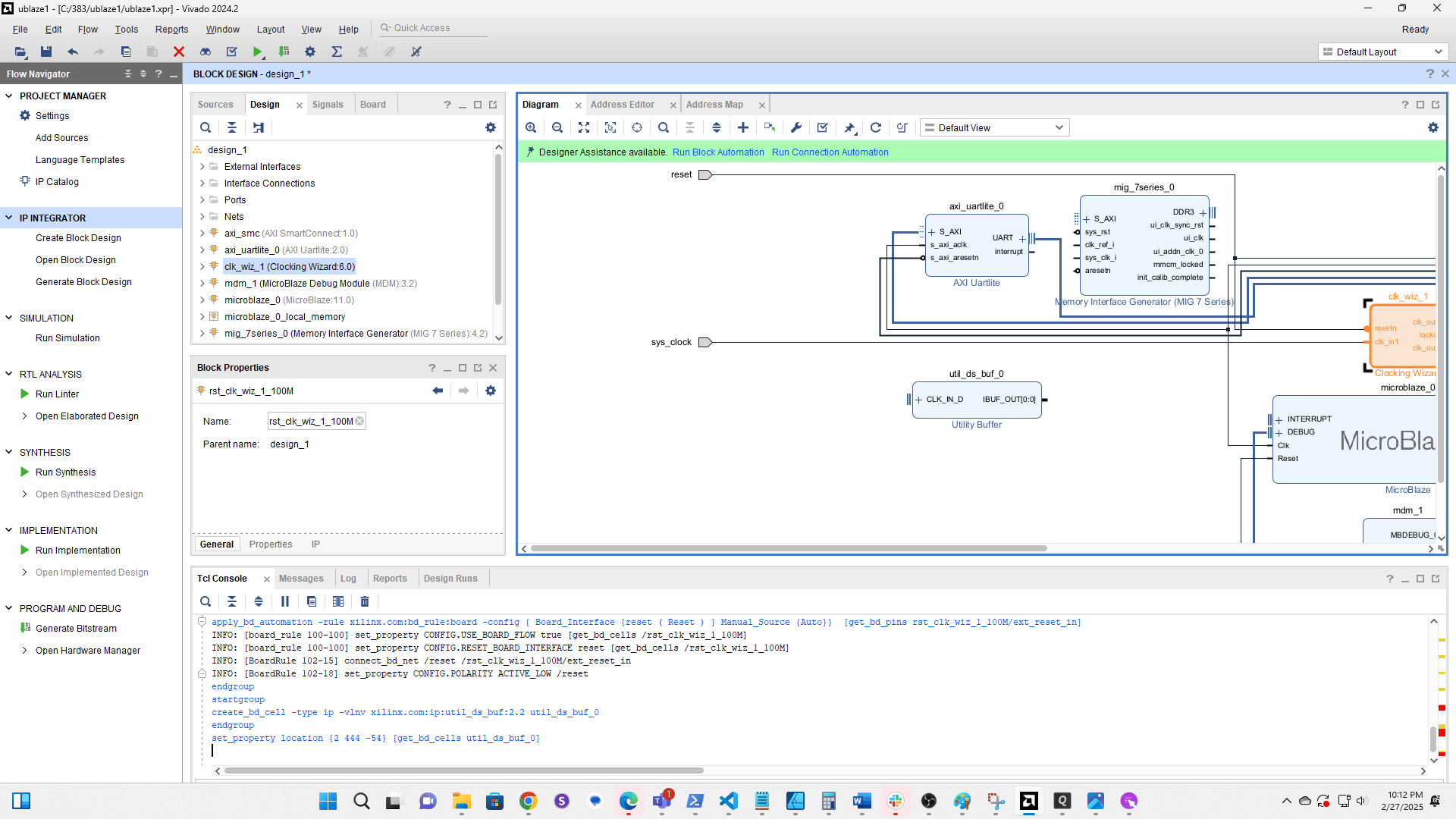
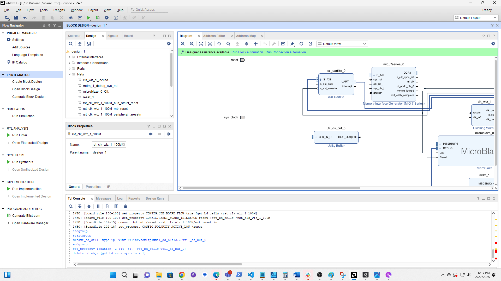
Click the connection from sys clk to clk wiz 1 and delete it
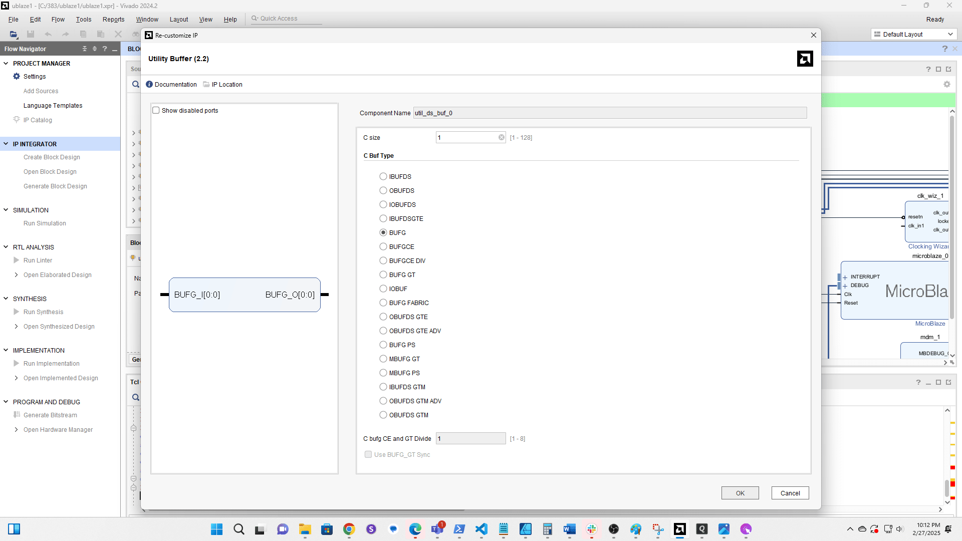
Double click the Utility Buffer to edit it
Change the type to BUFG
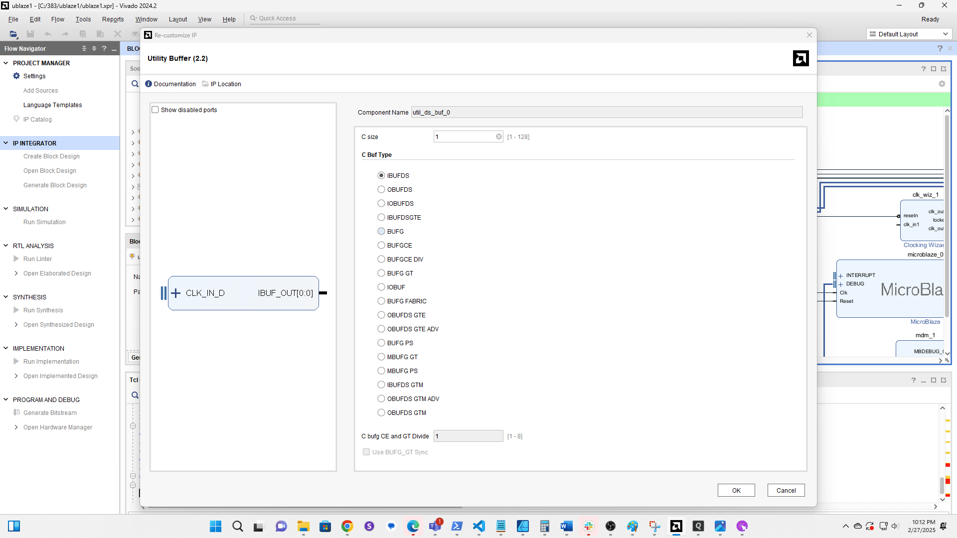
Click here
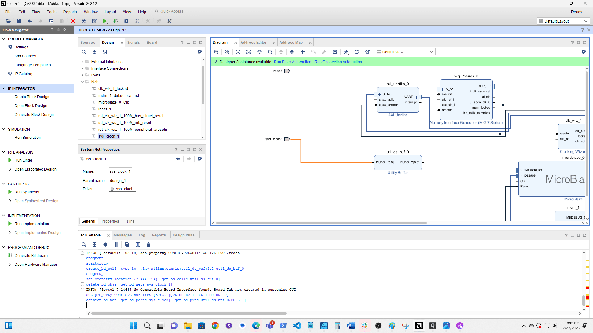
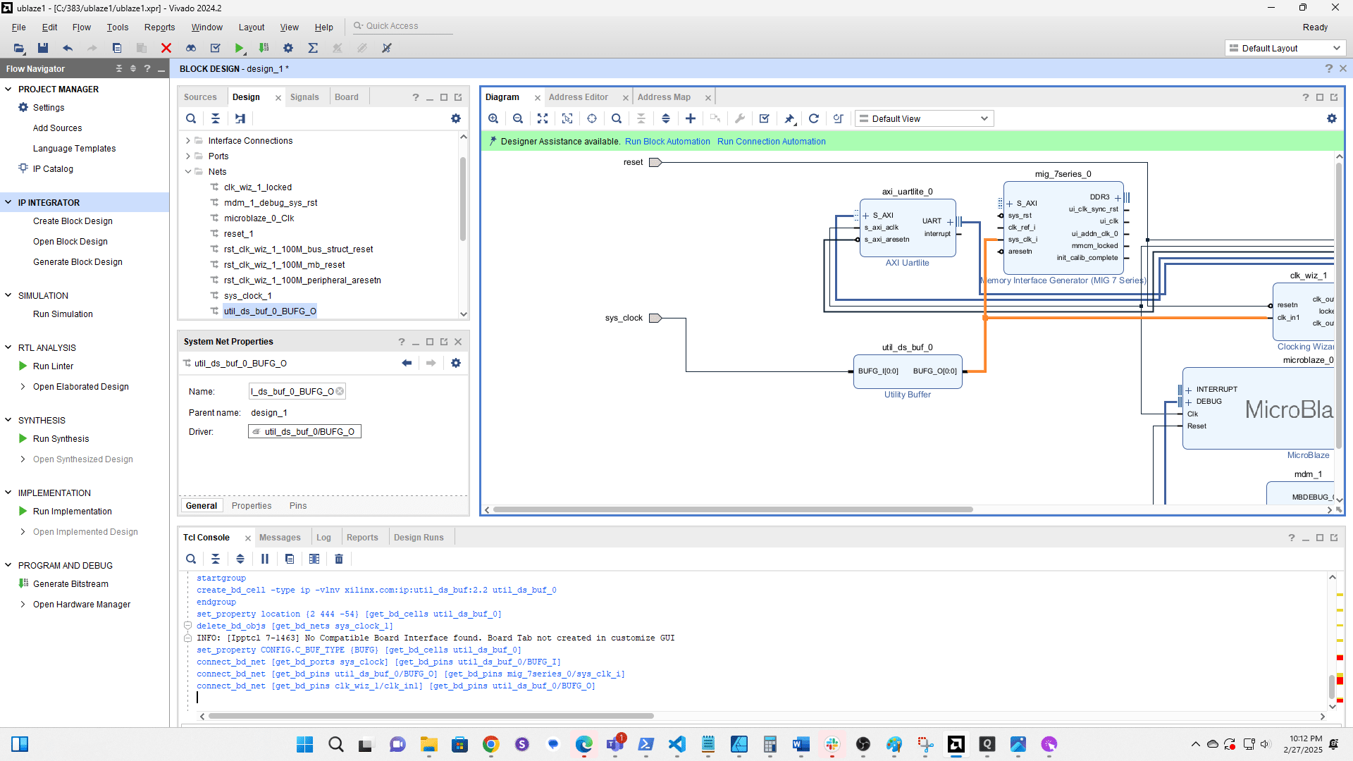
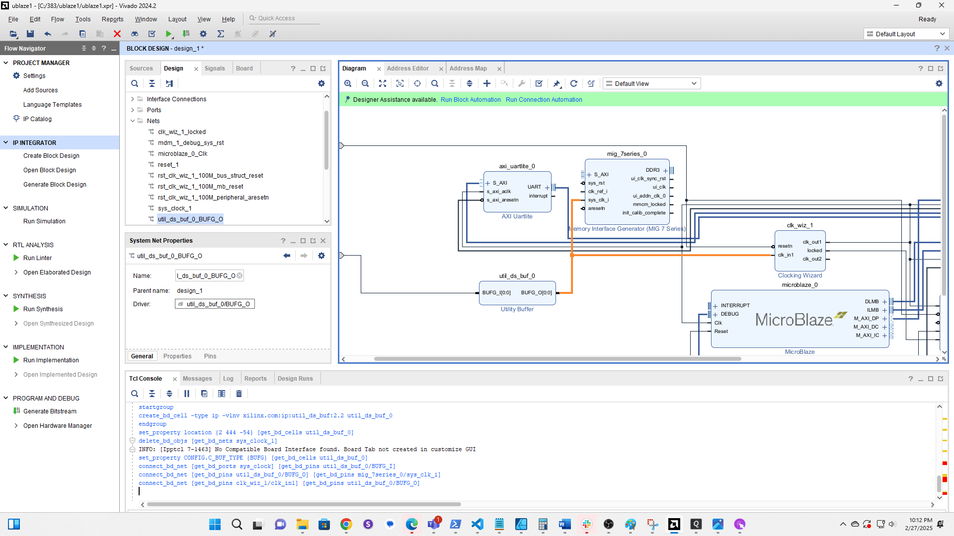
Click and drag a new connection from sys clk to the input on the Utility Buffer
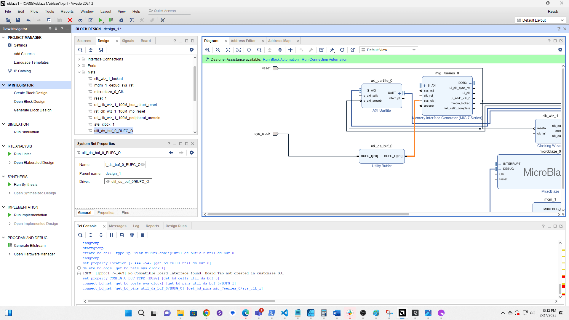
Click and drag a connection from the output of the Utility Buffer to sys clk i on the MIG
Click and drag to create a connection from the Utility Buffer output to clk in1 on Clk Wiz 1
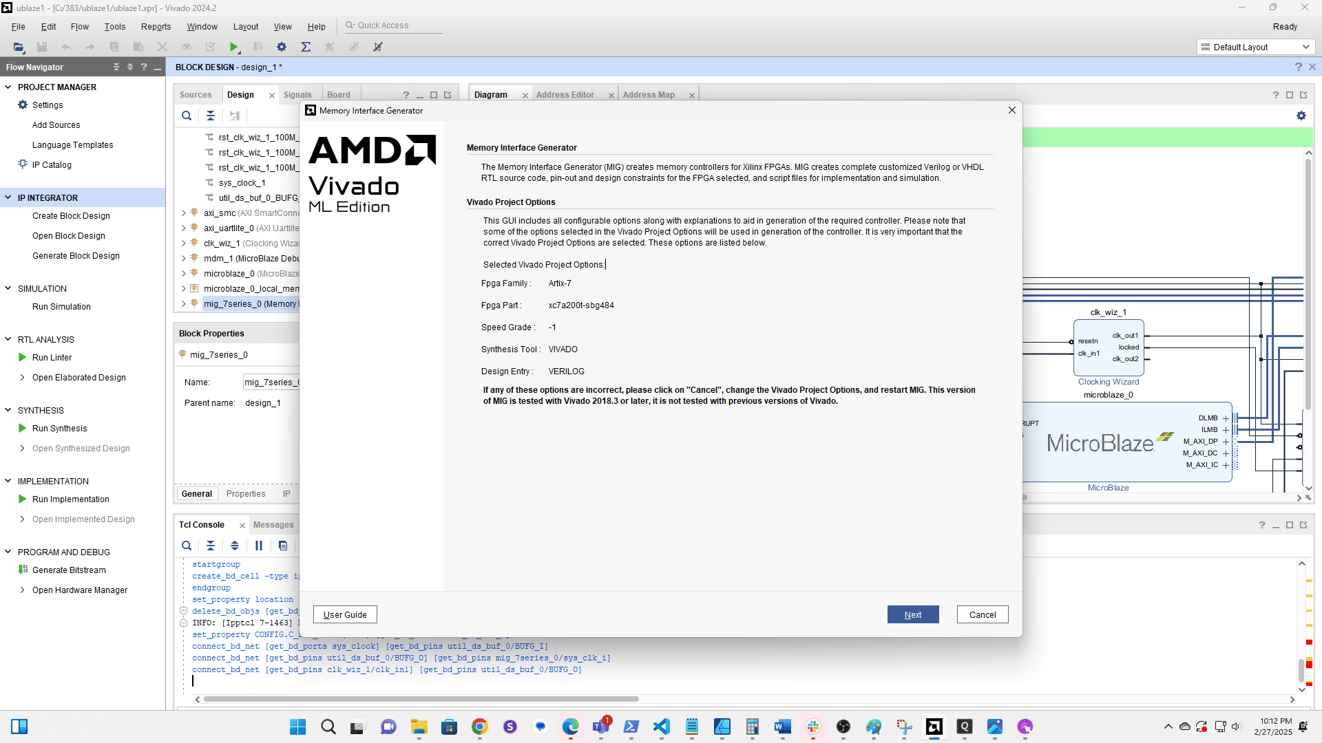
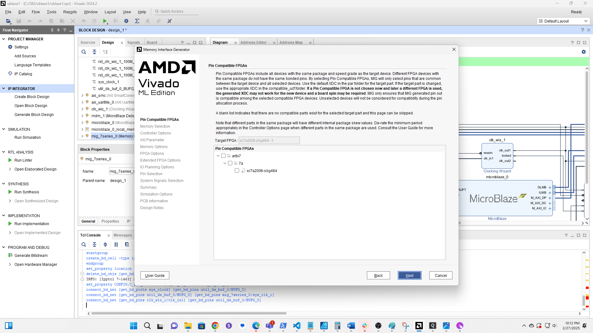
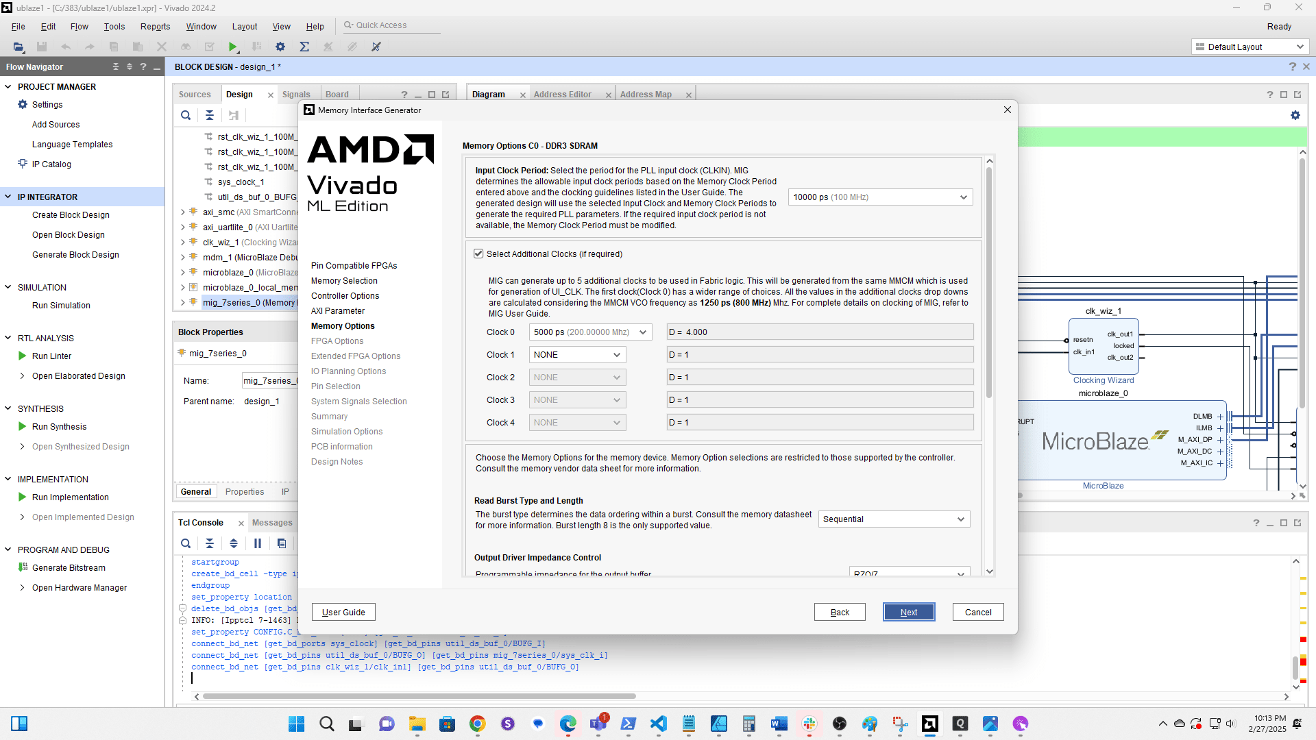
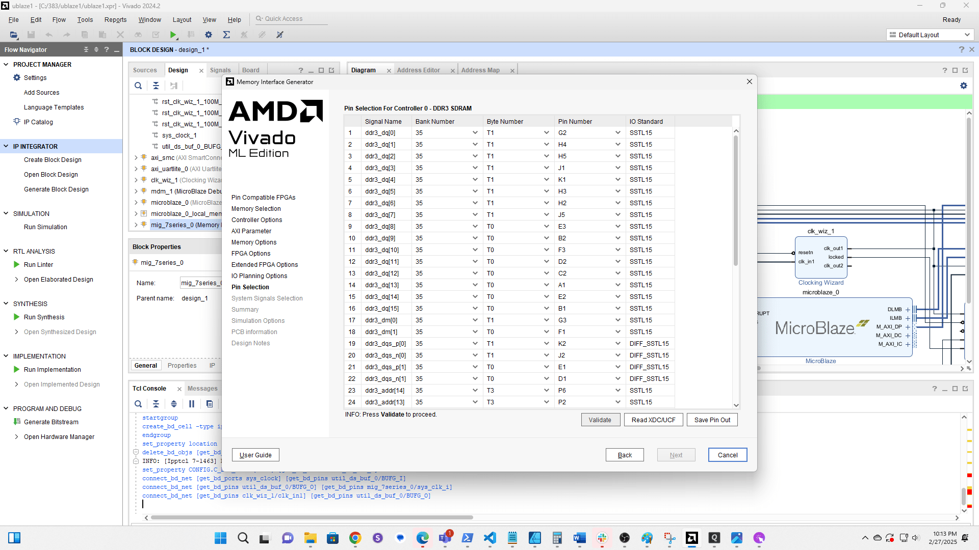
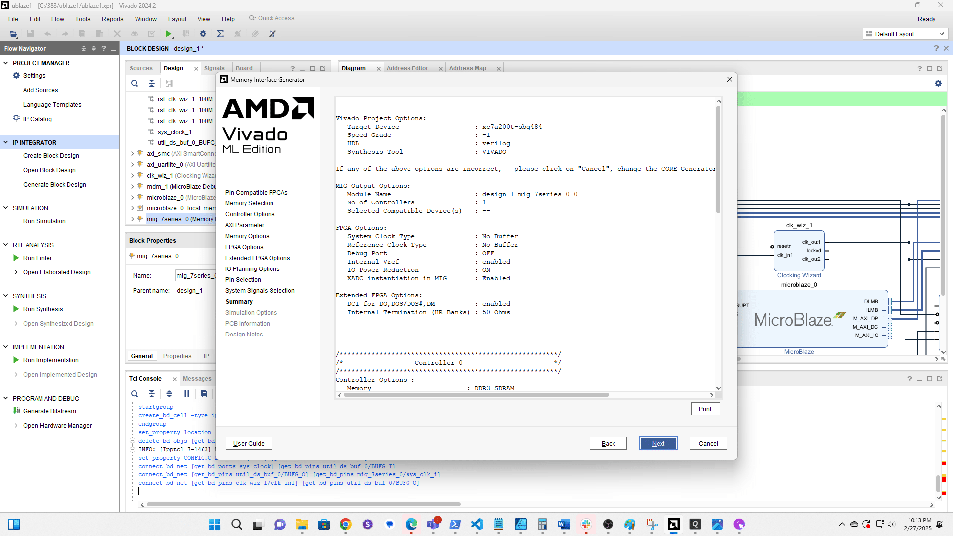
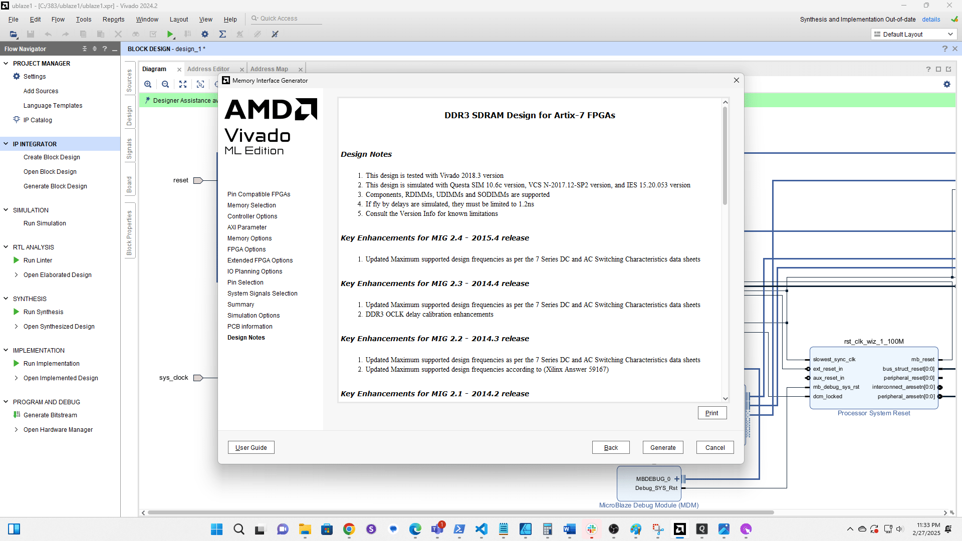
Double click the MIG to edit it
Click here
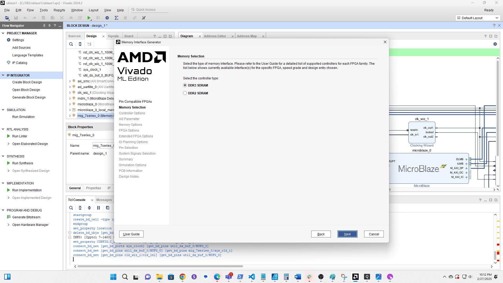
Click here
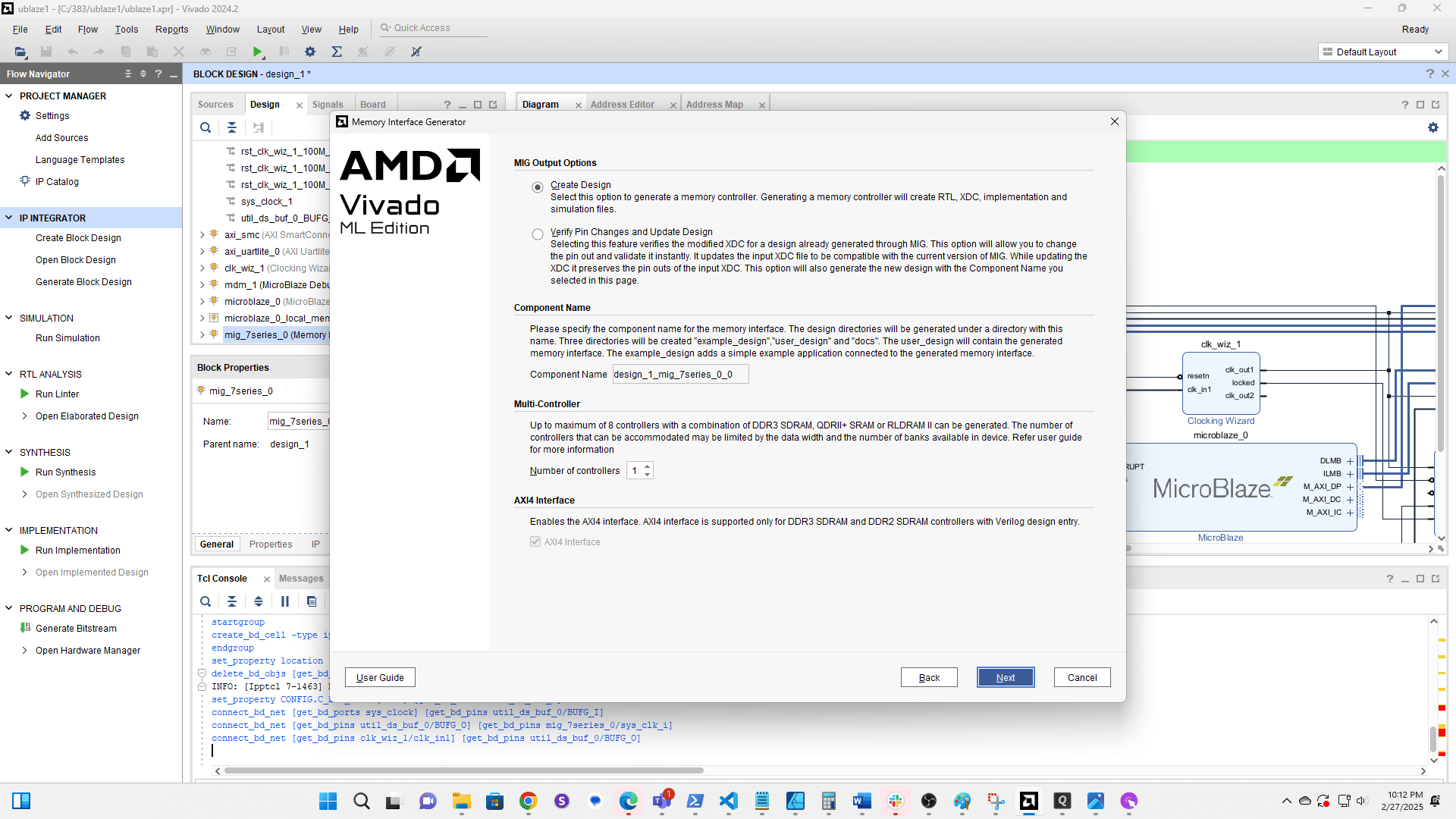
Click here
Click here
Click here
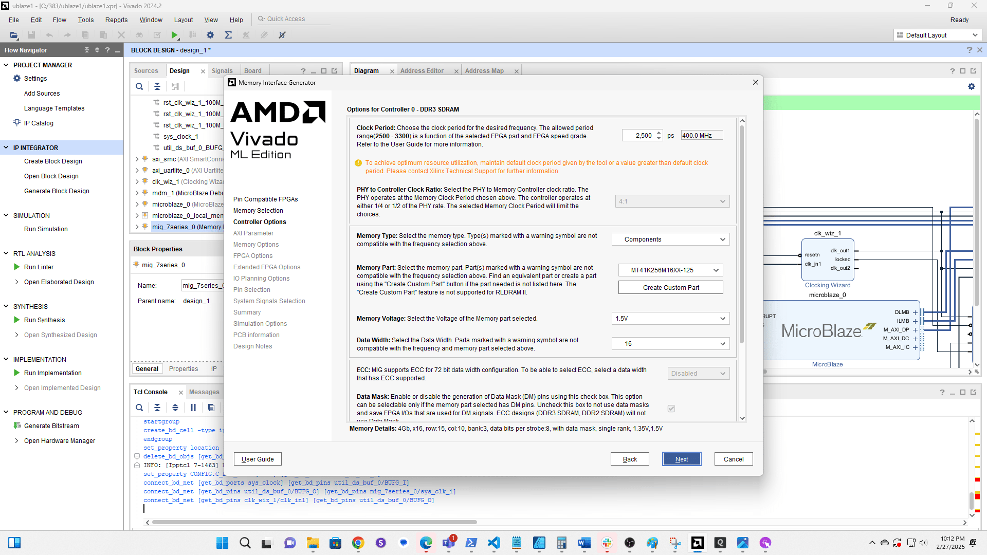
Click here
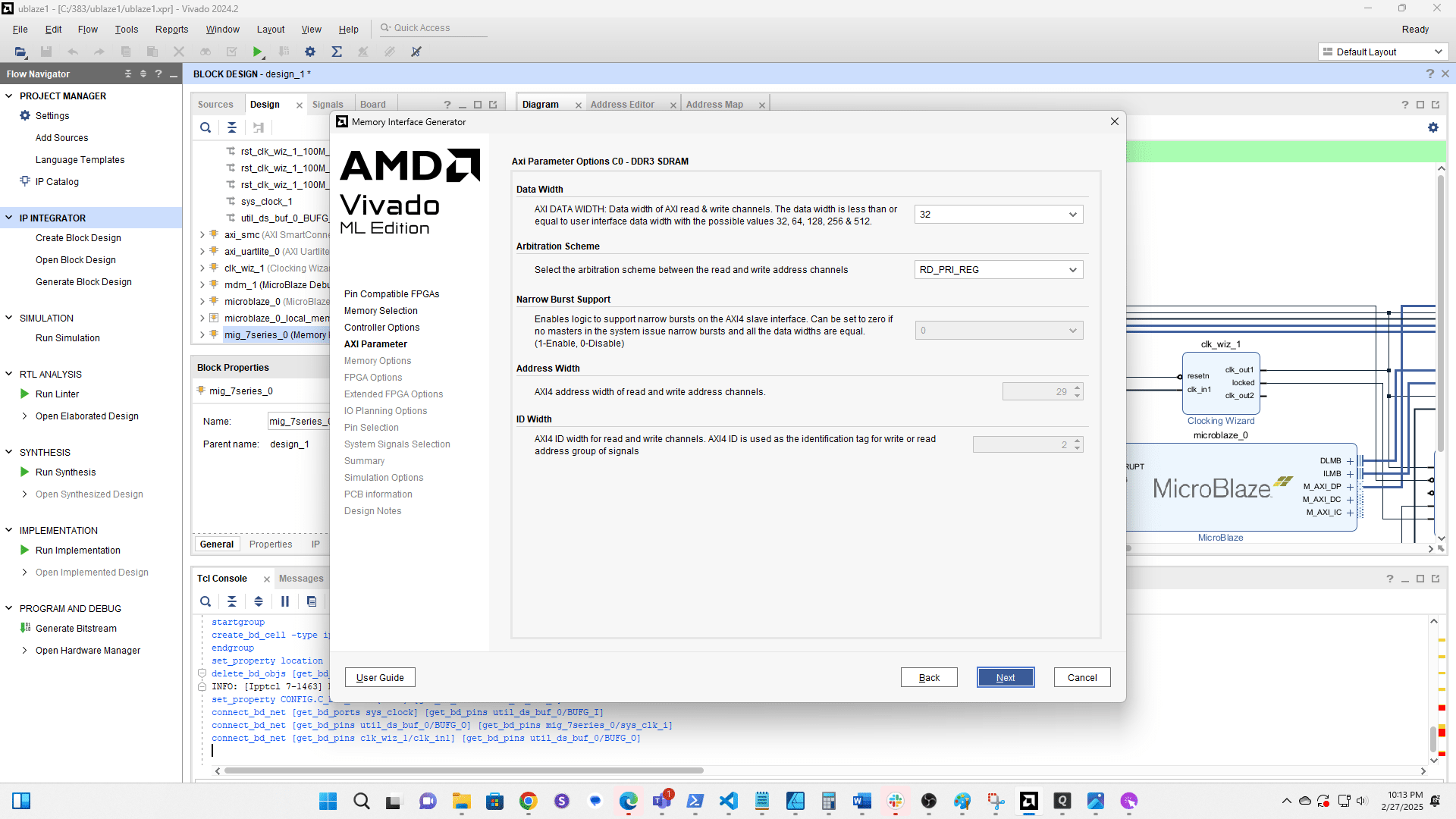
Click here
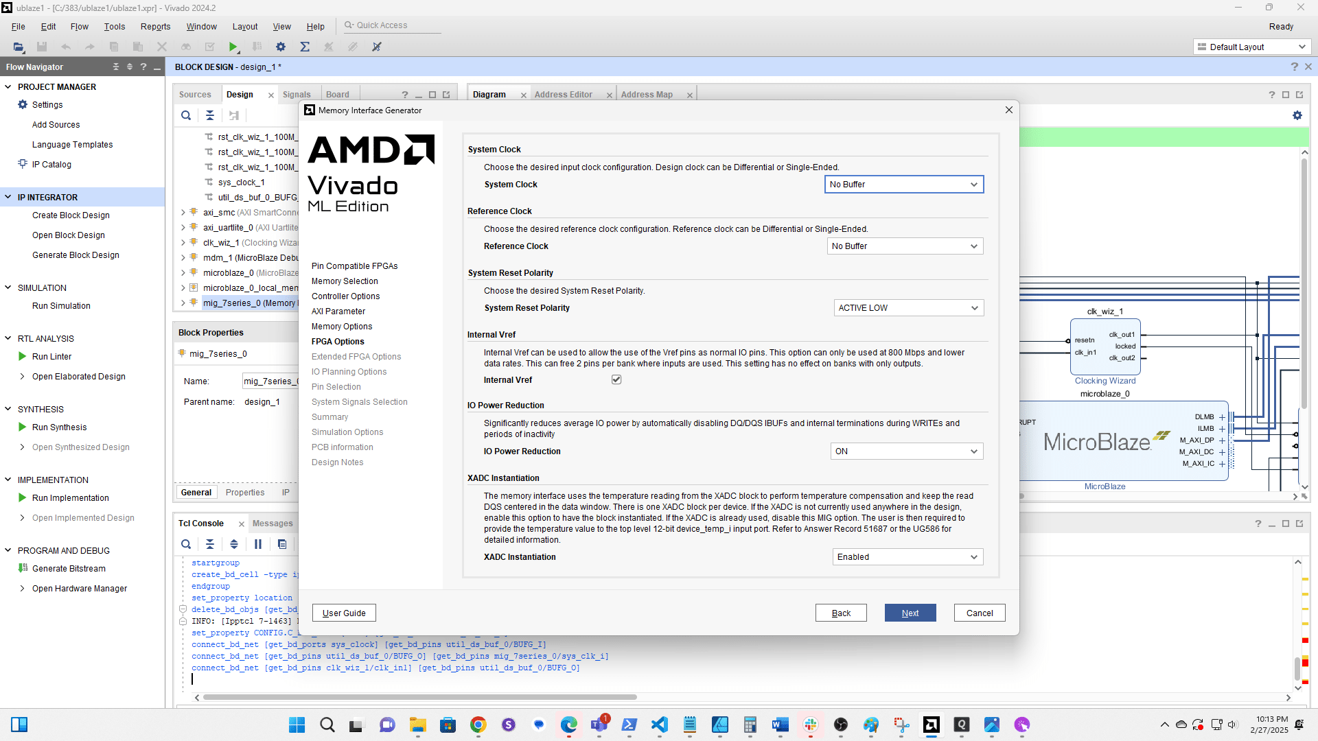
Change the System Clock configuration to No Buffer

Click here
Click here
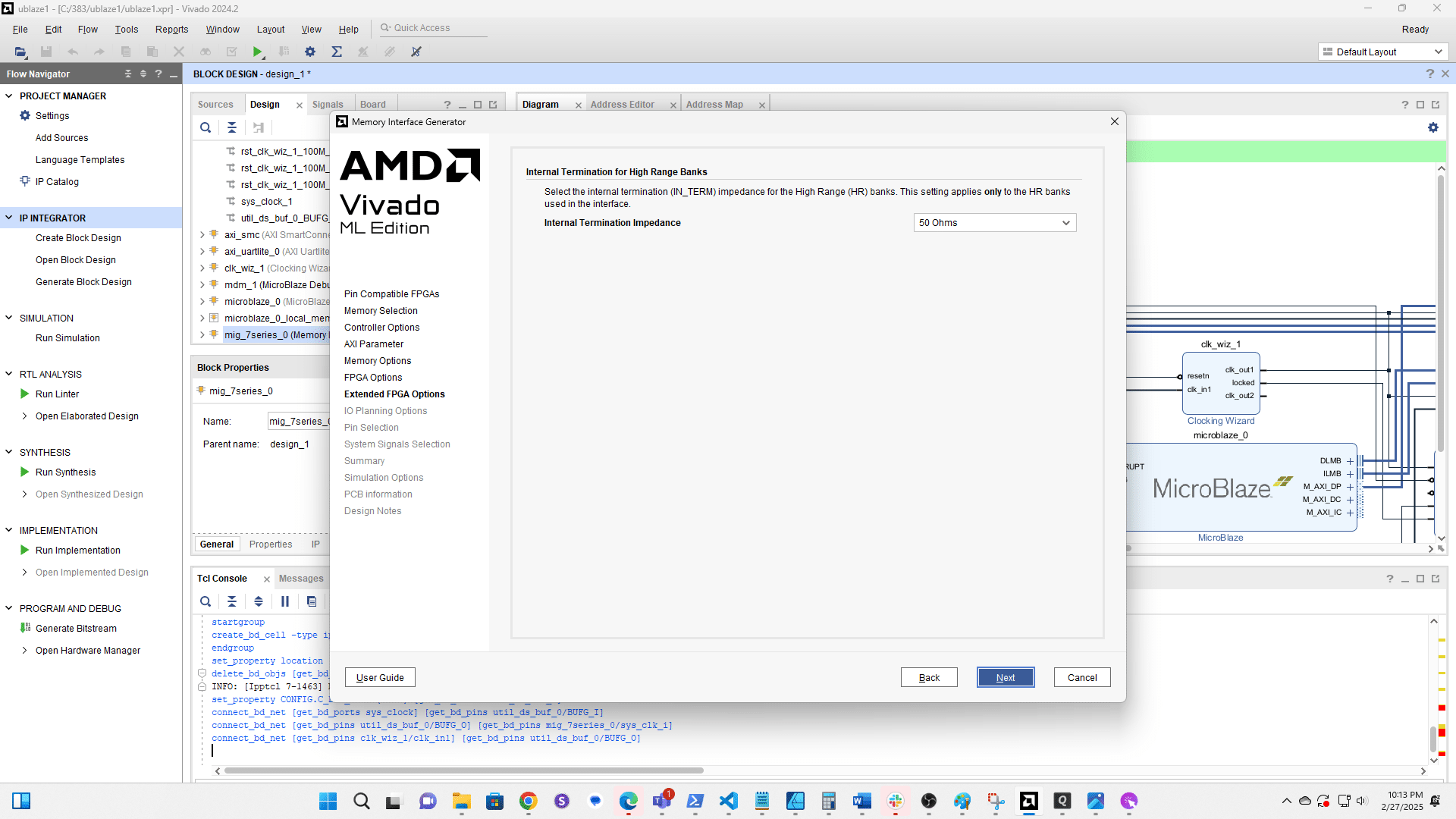
Click here
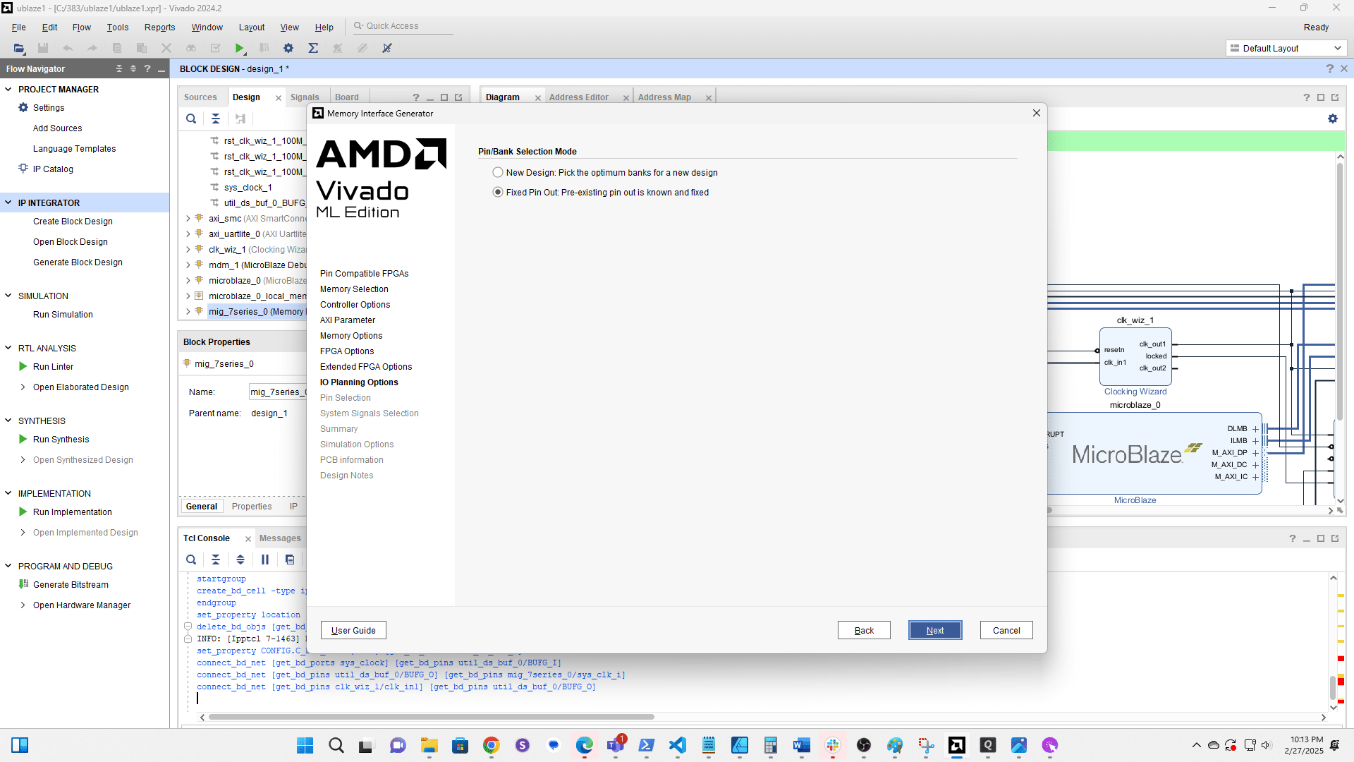
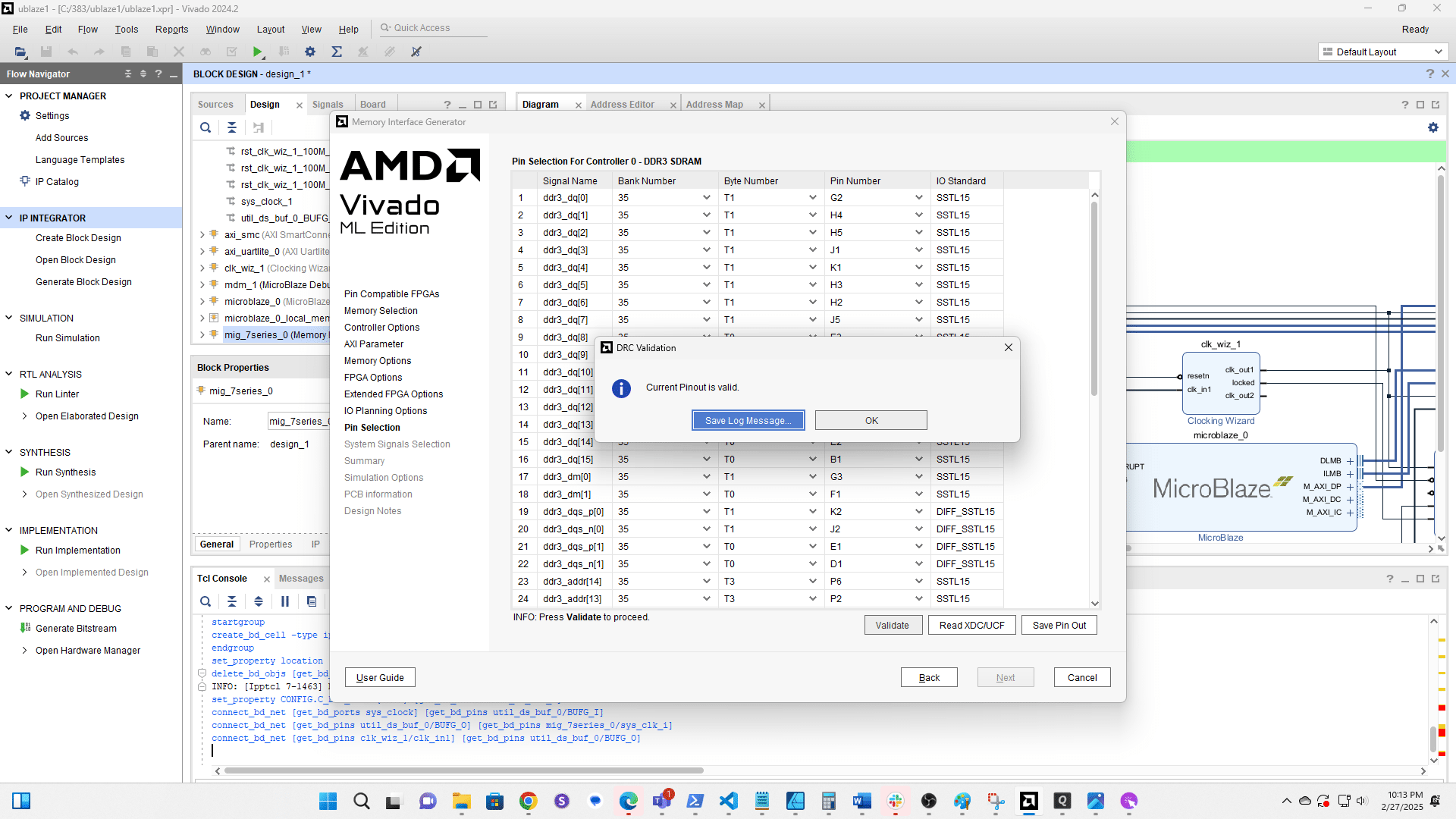
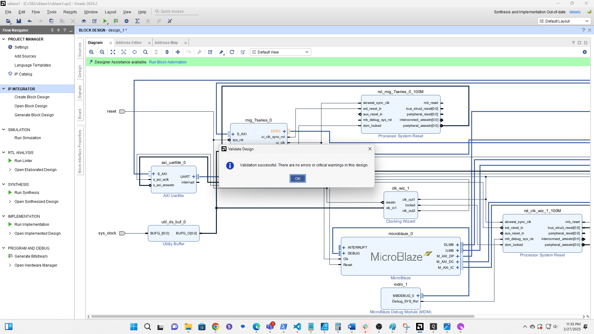
Click Validate
Click OK
Click here
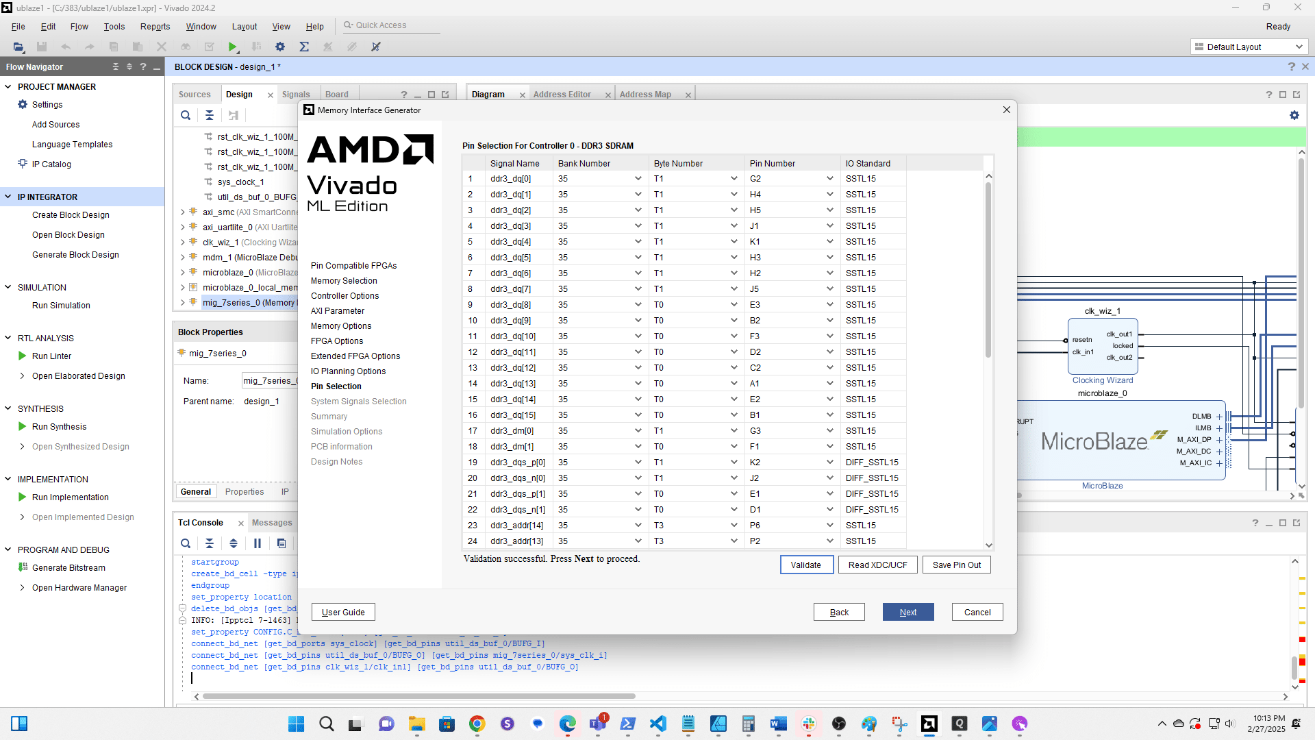
Click here
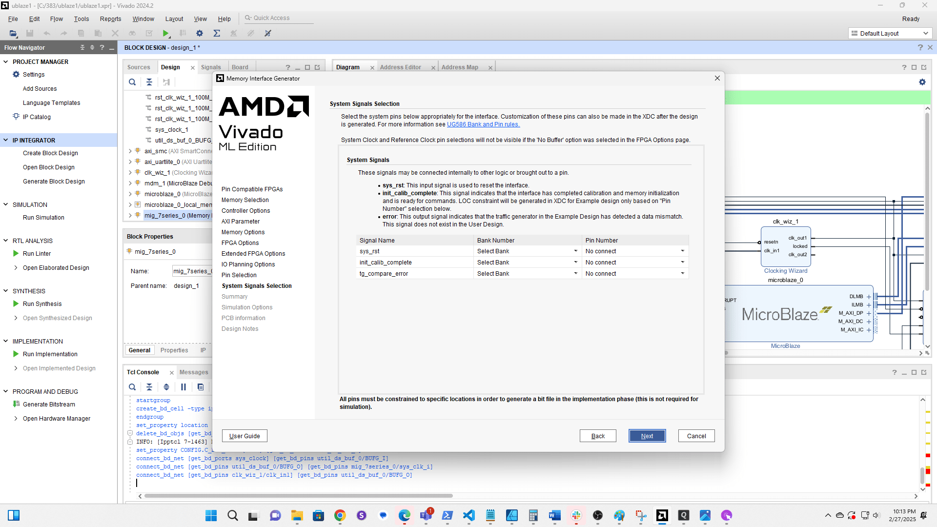
Click here
Click here
Click here
Click here
Click Generate
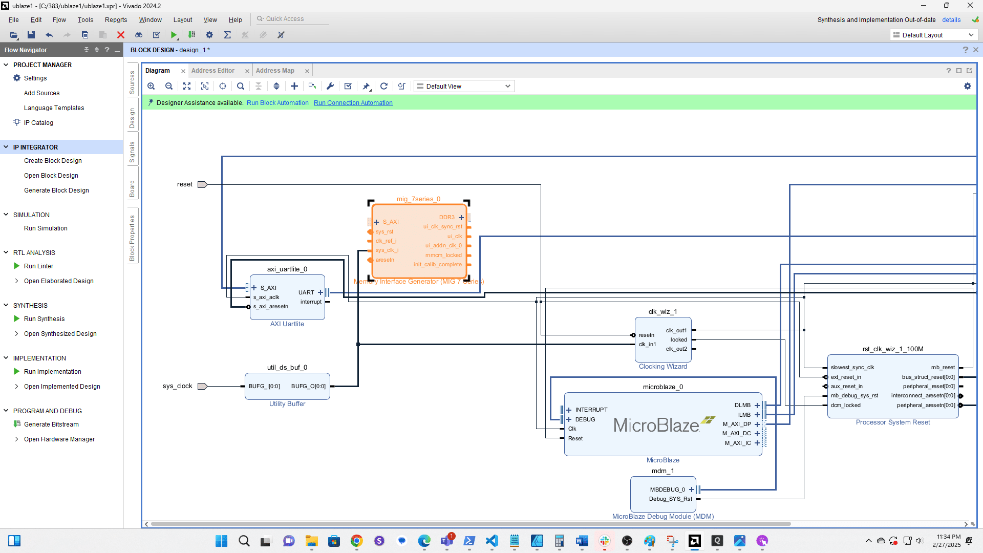
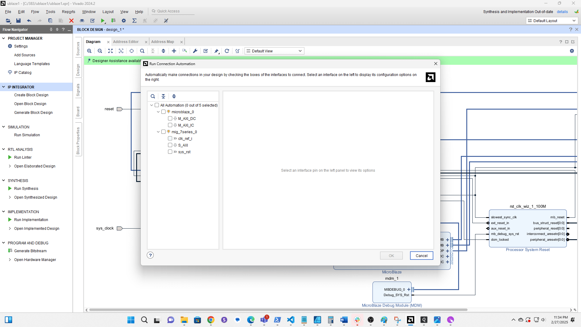
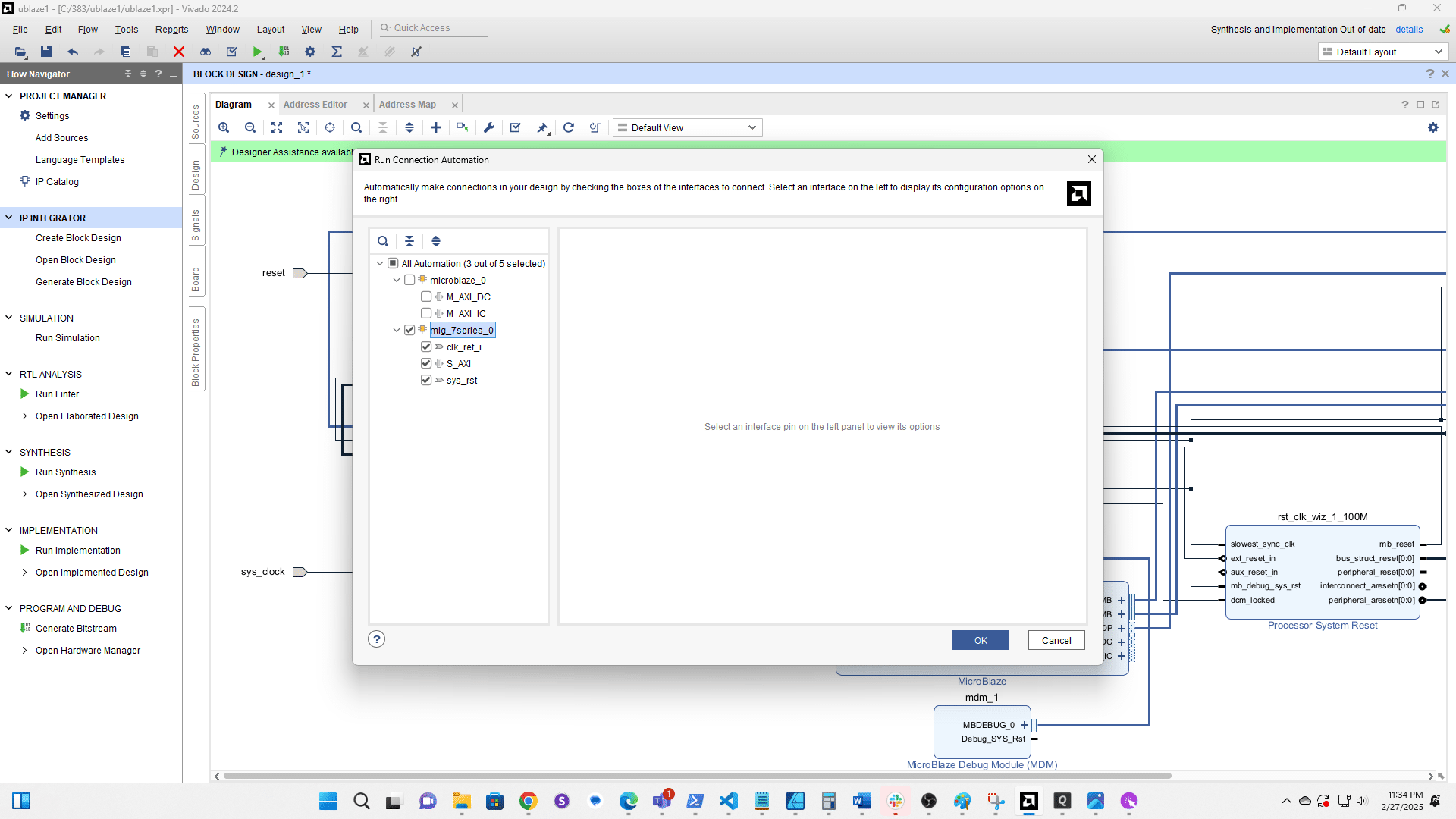
Click Run Connection Automation
Click clk ref i
Click here
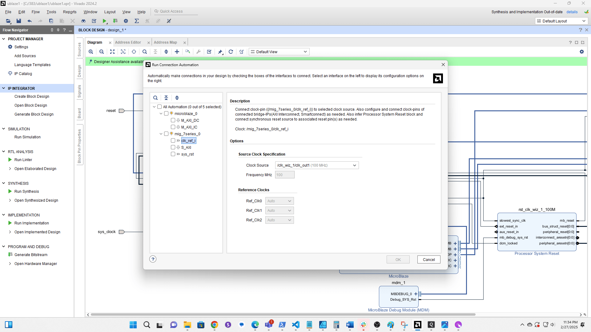
Select the 200 MHz clock from Clk Wiz 1
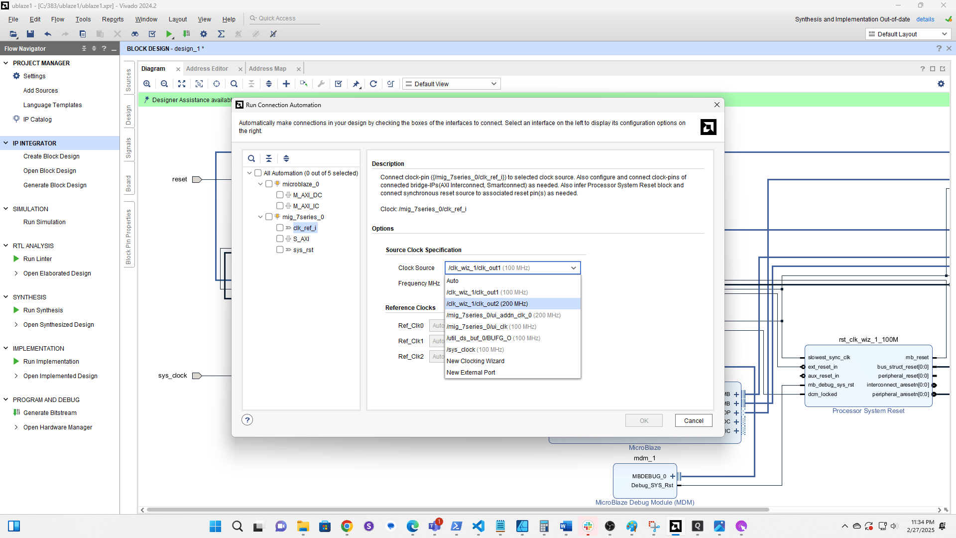
Click here

Click here
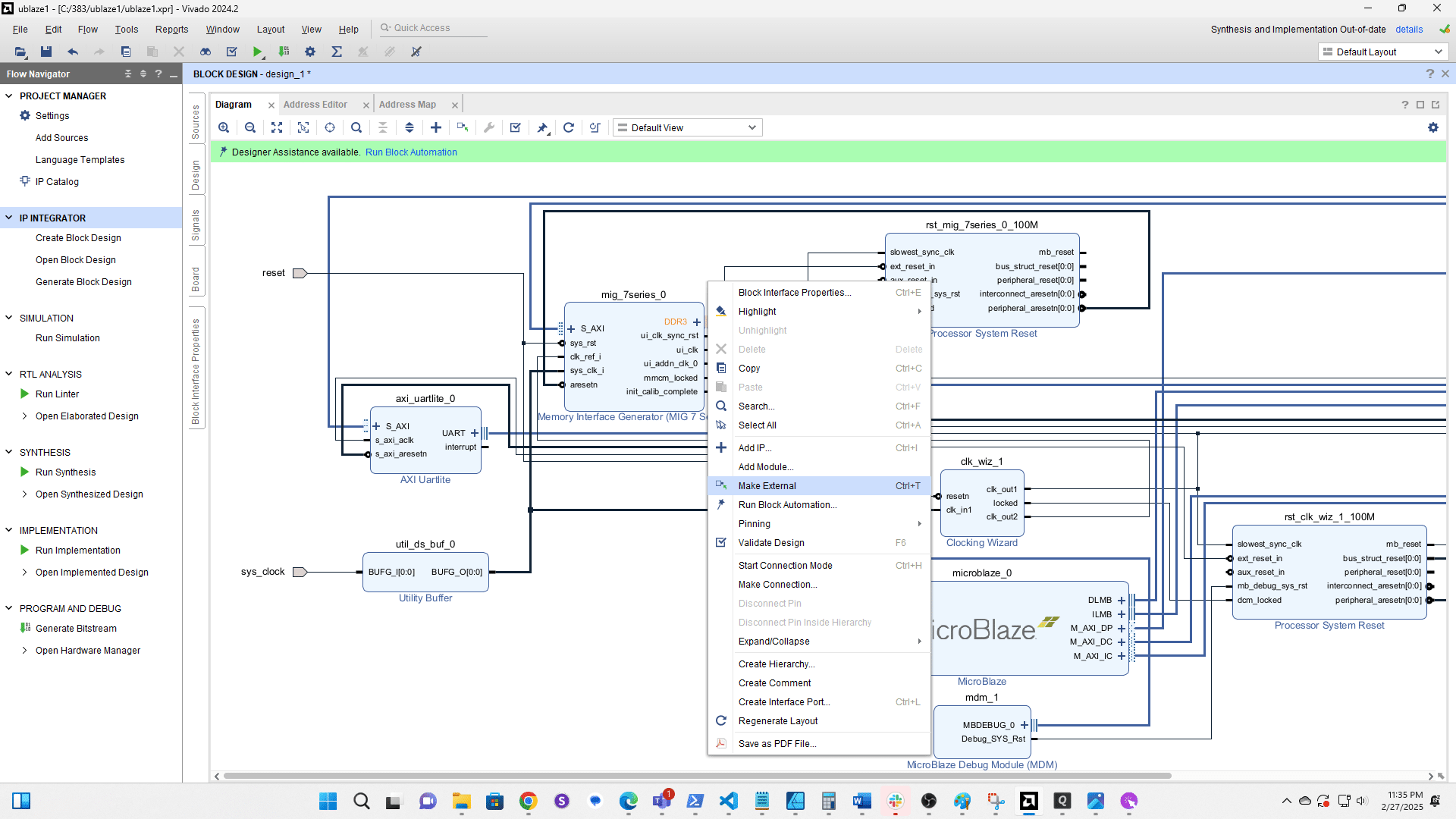
Right click the three vertical lines next to the DDR3 port
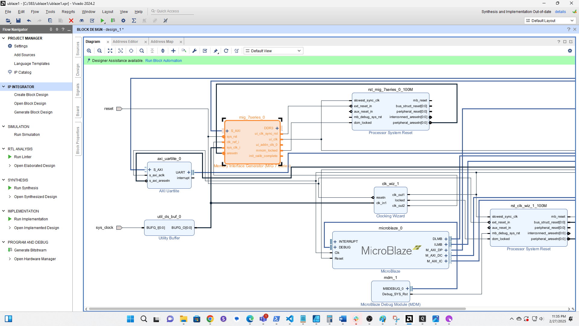
Select Make External
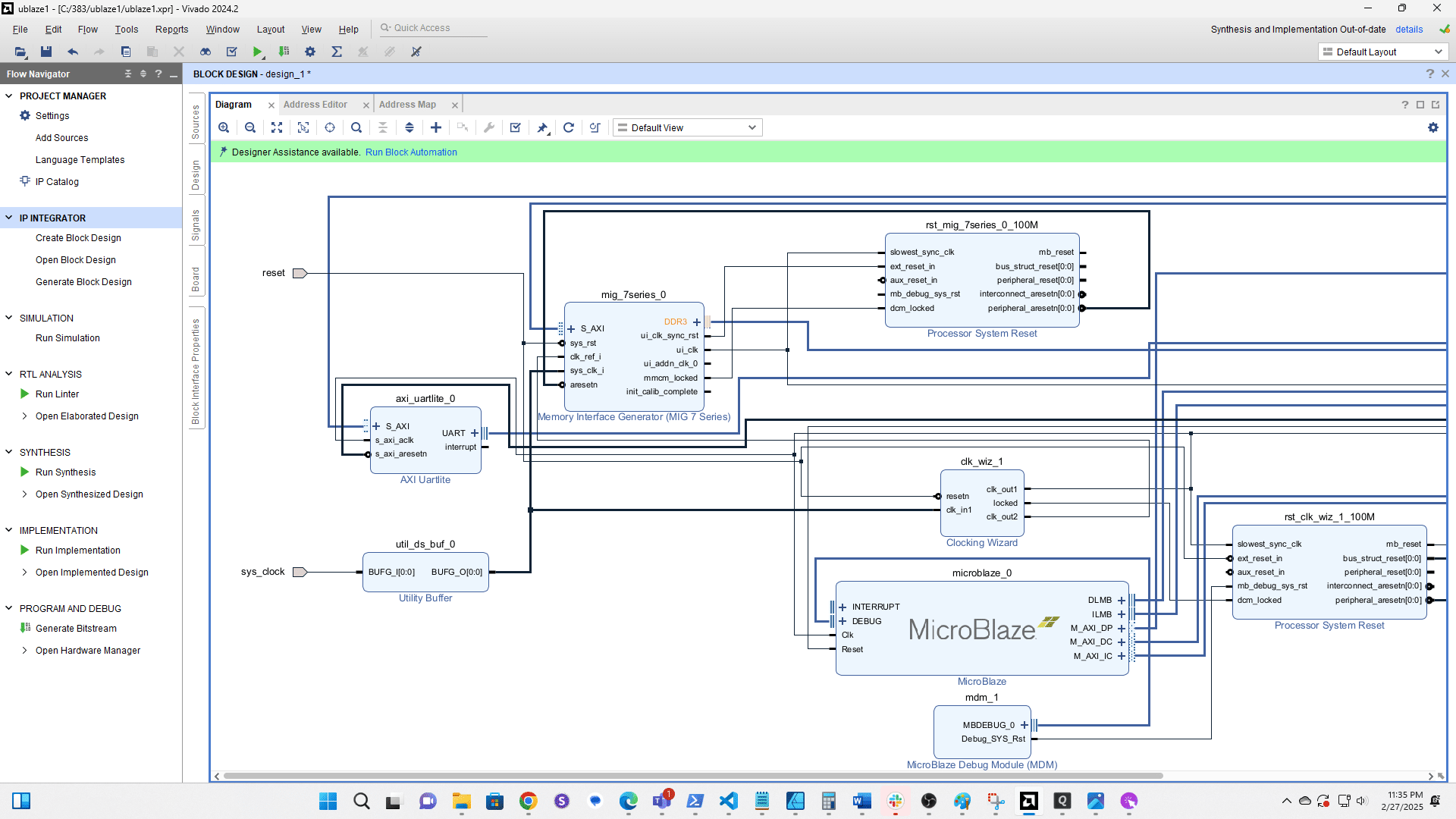
Click the checkbox to validate the design

Click Sources
Click here
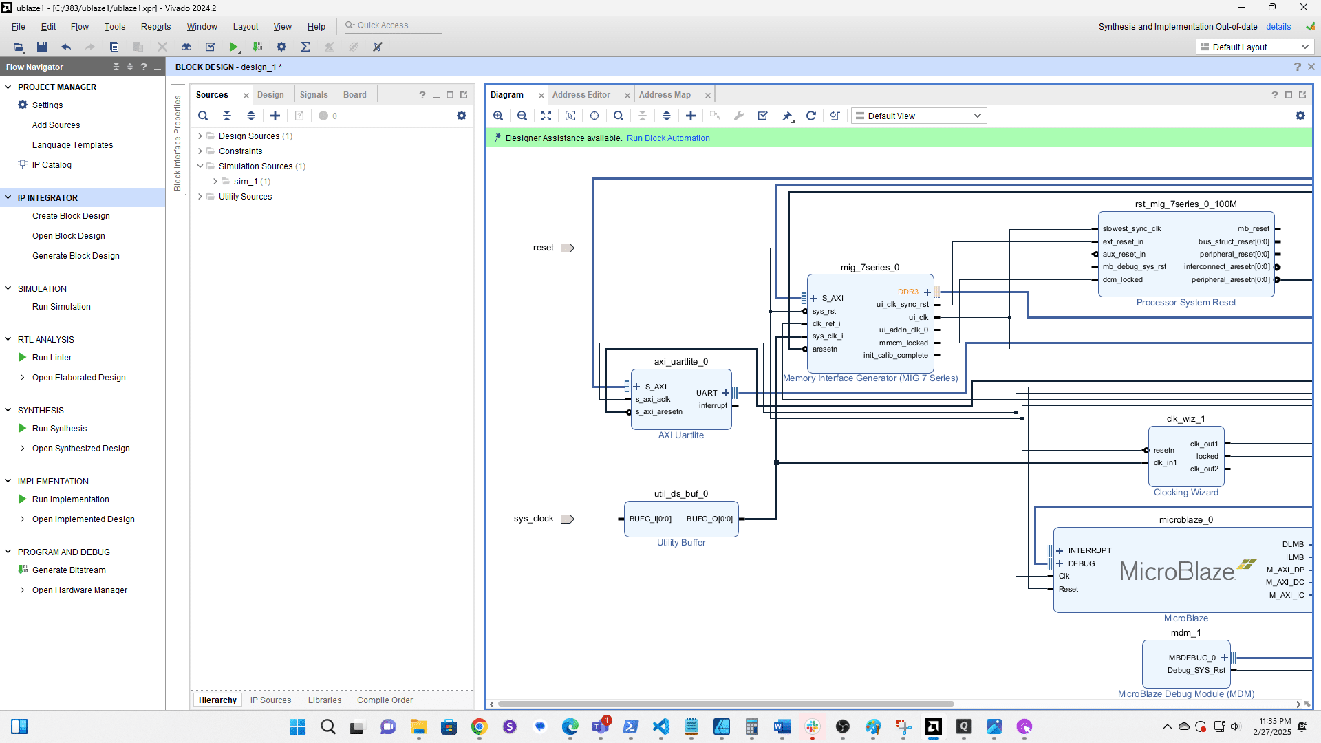
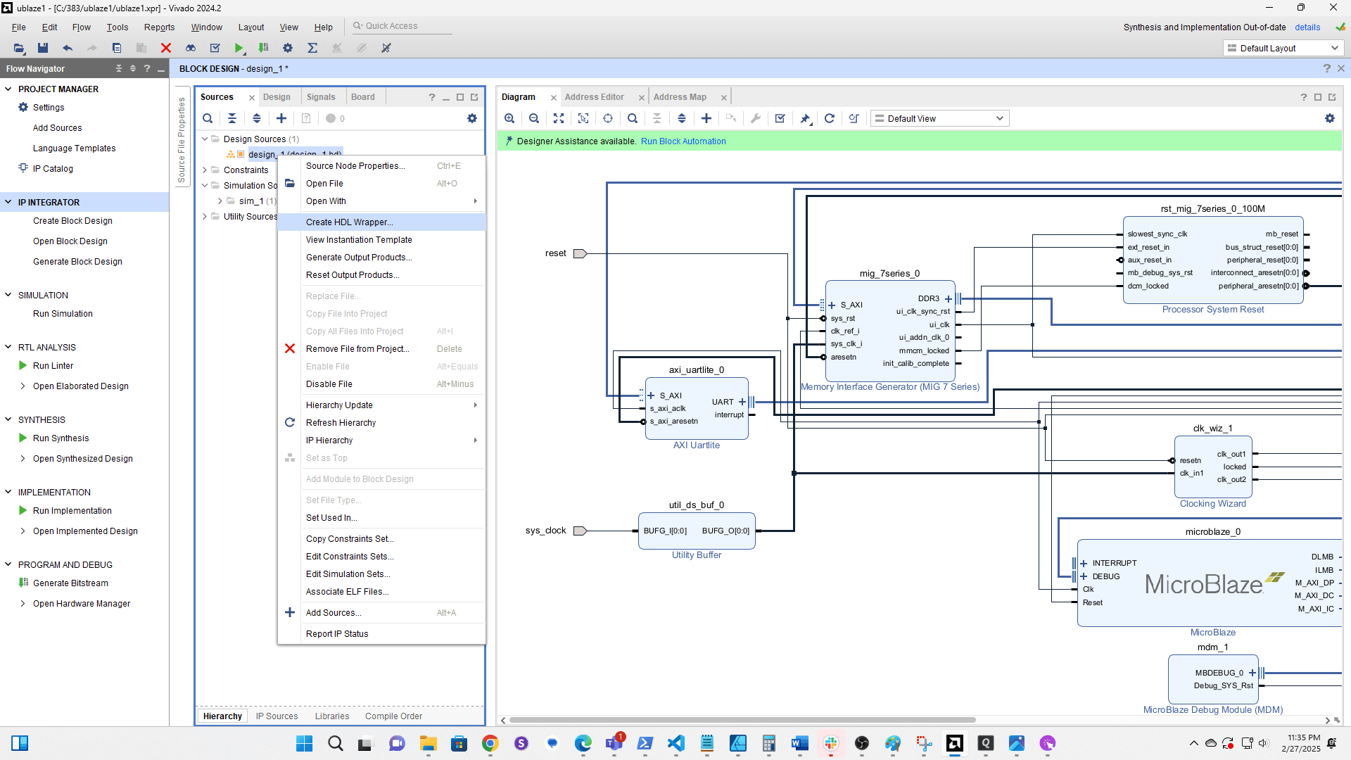
Right click the block design
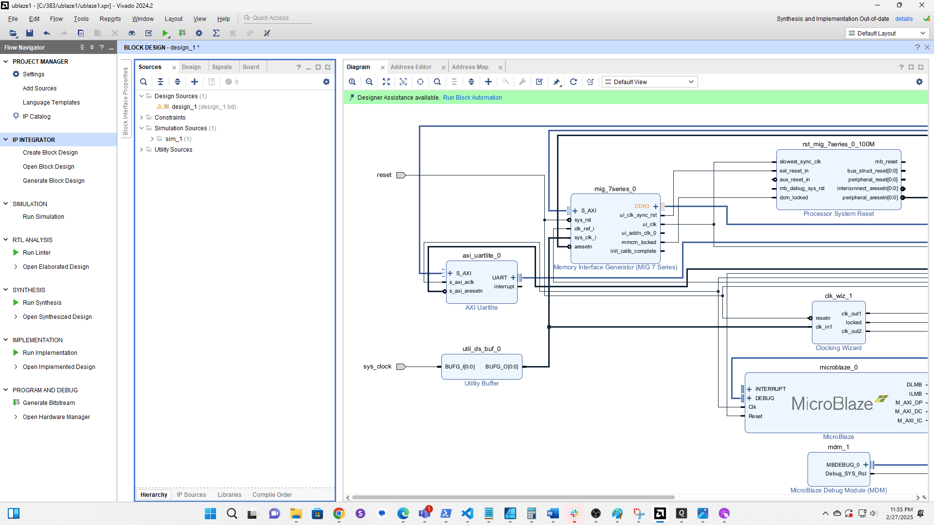
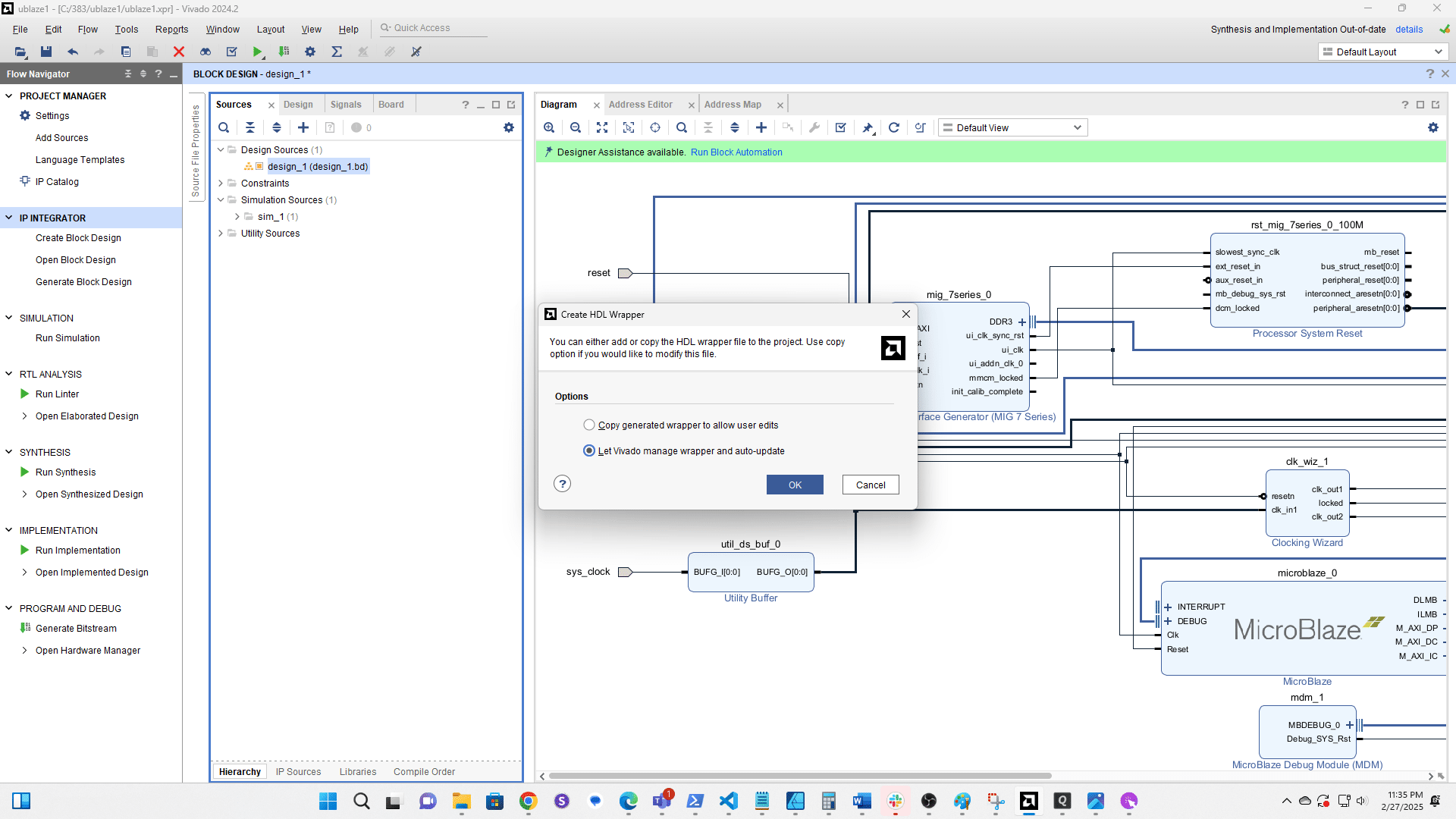
Choose Create HDL Wrapper
Let Vivado manage it
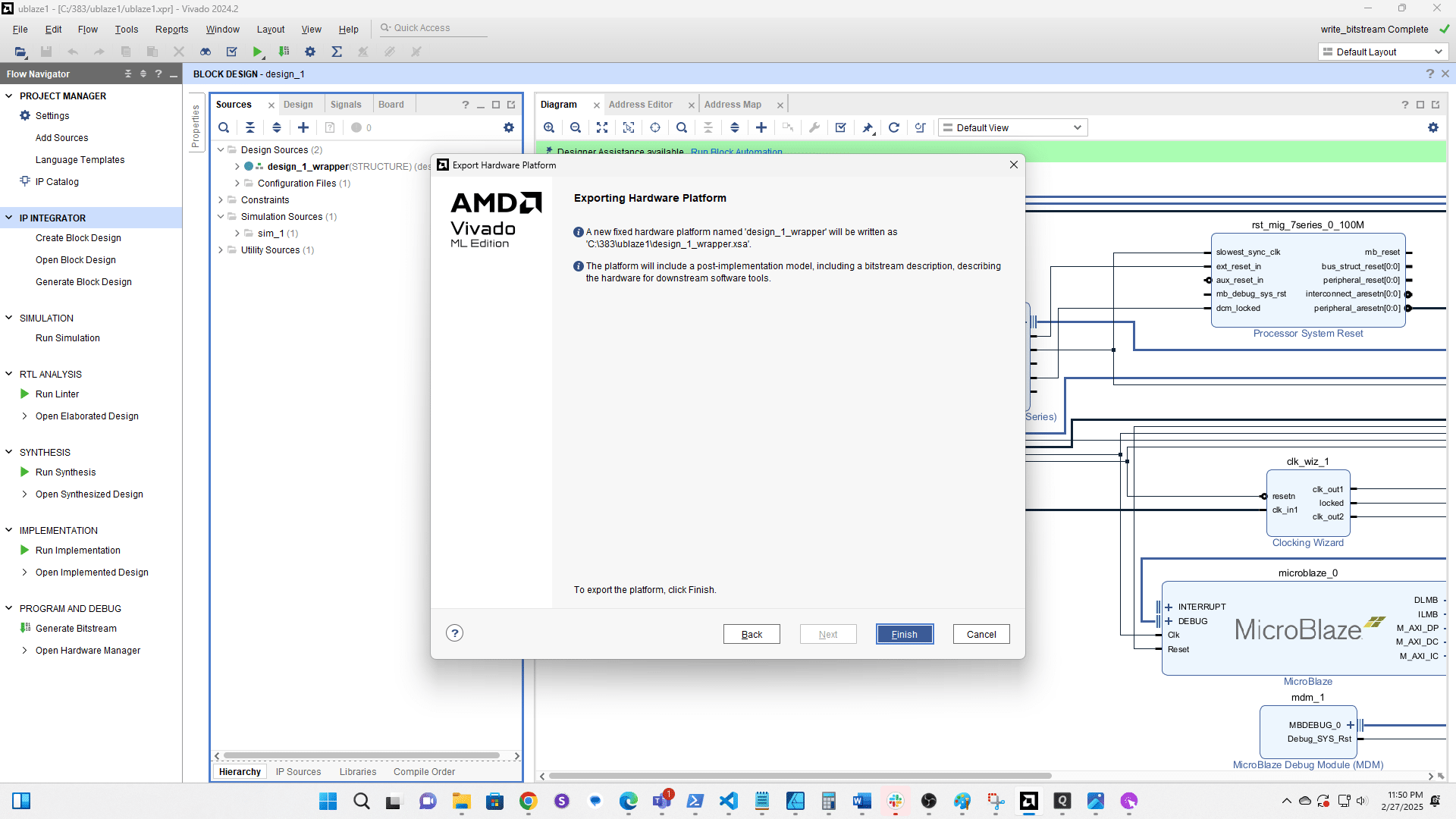
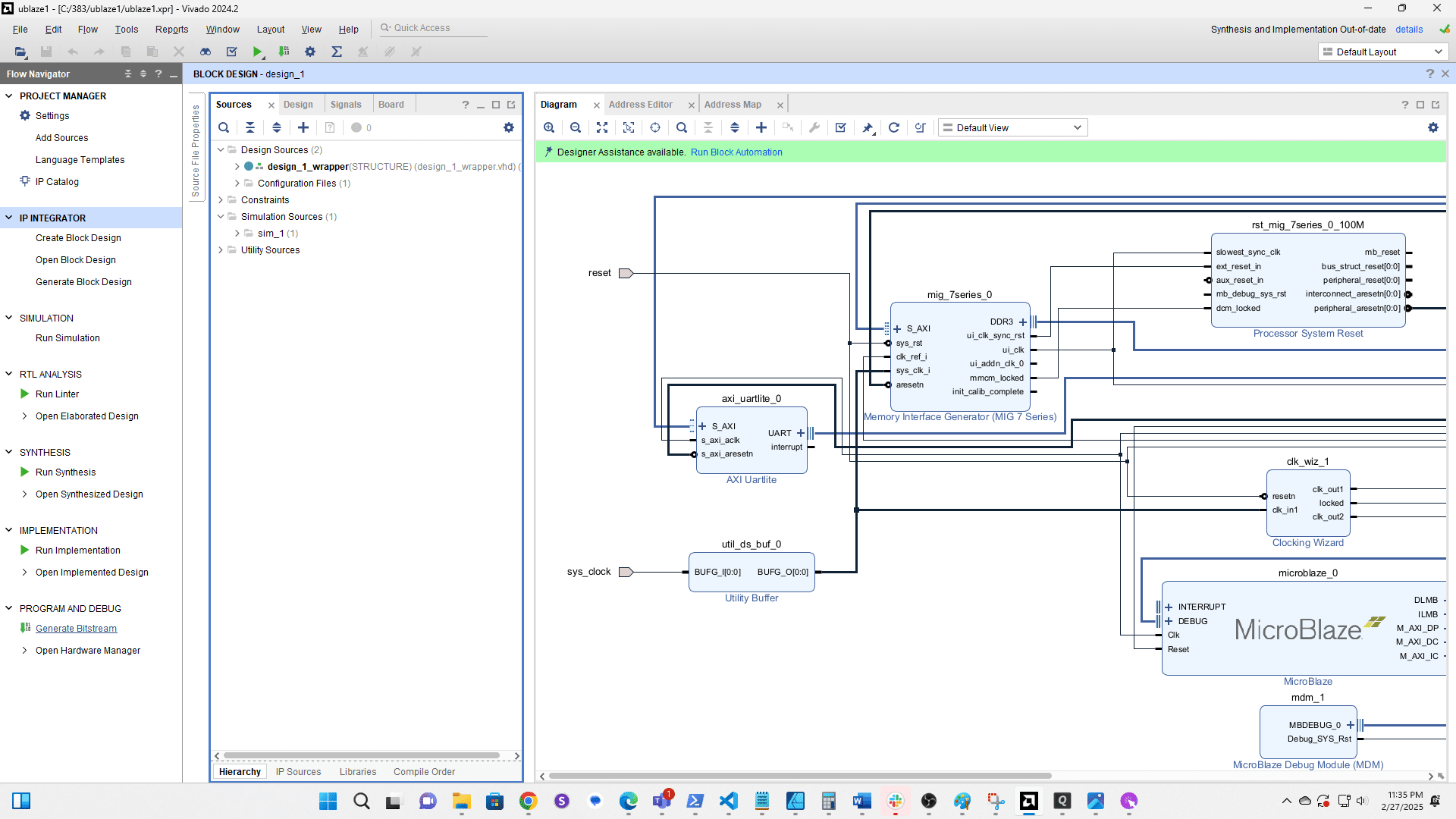
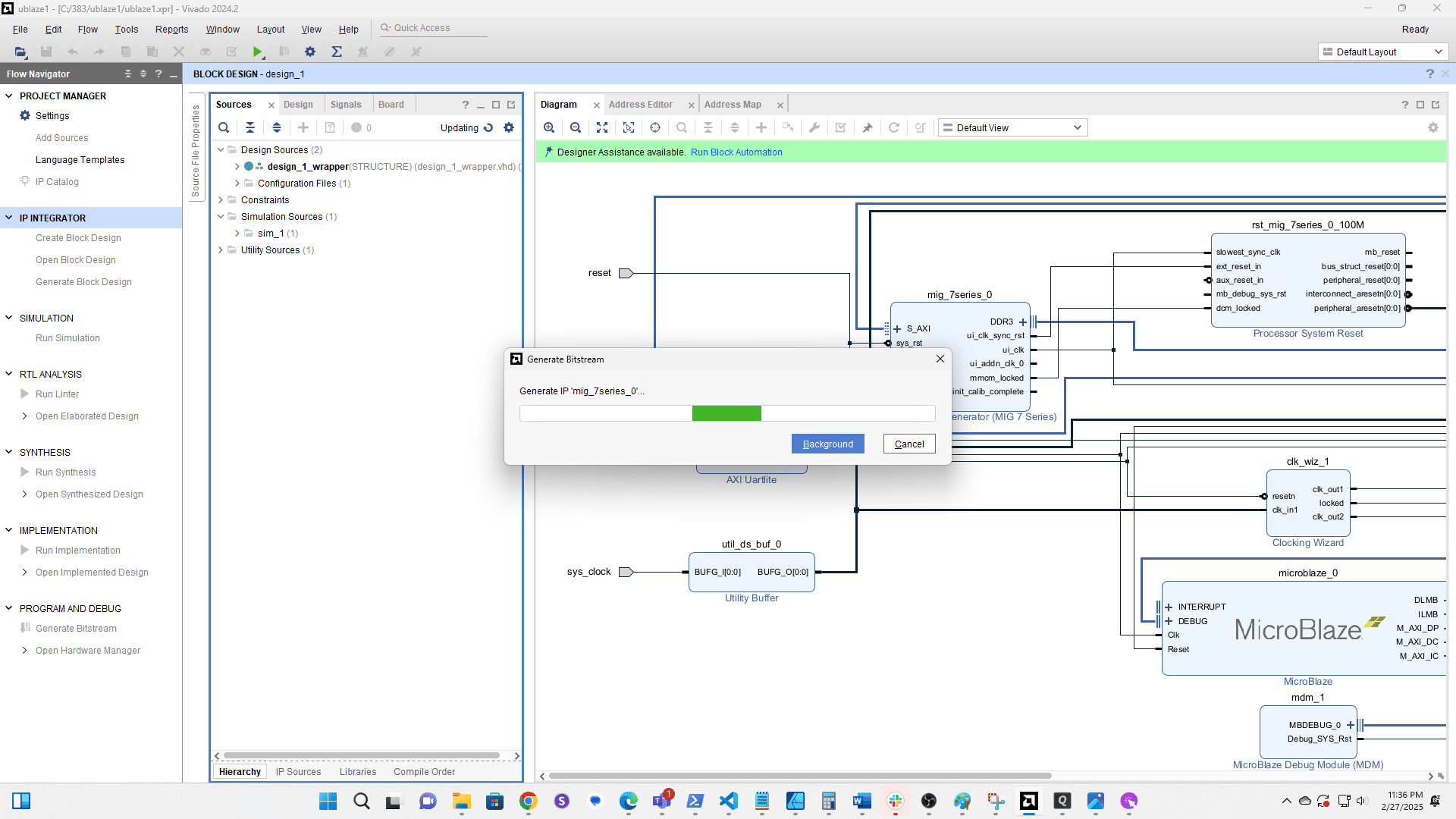
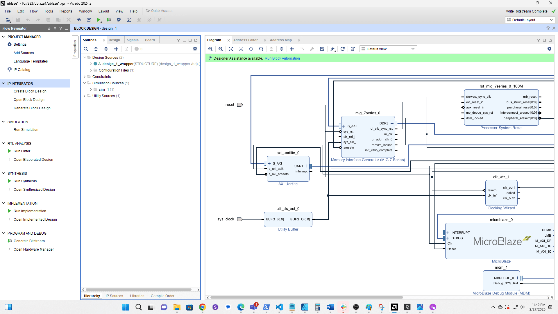
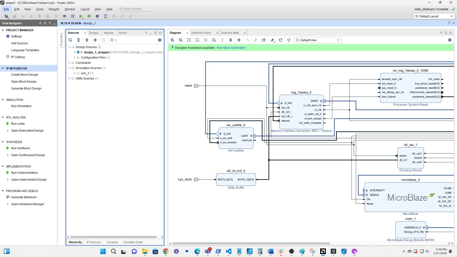
Generate the Bitstream (aka Popcorn Time 🍿). Note: If ui_addn_clk_0 or init_calib_complete on the MIG are wired to external ports delete the ports and wires before generating the bitstream.
Click File
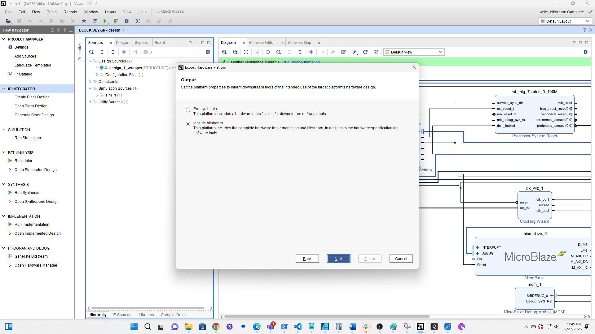
Select Export then Export Hardware
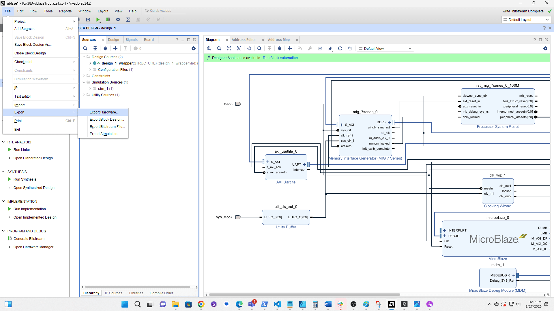
Click here
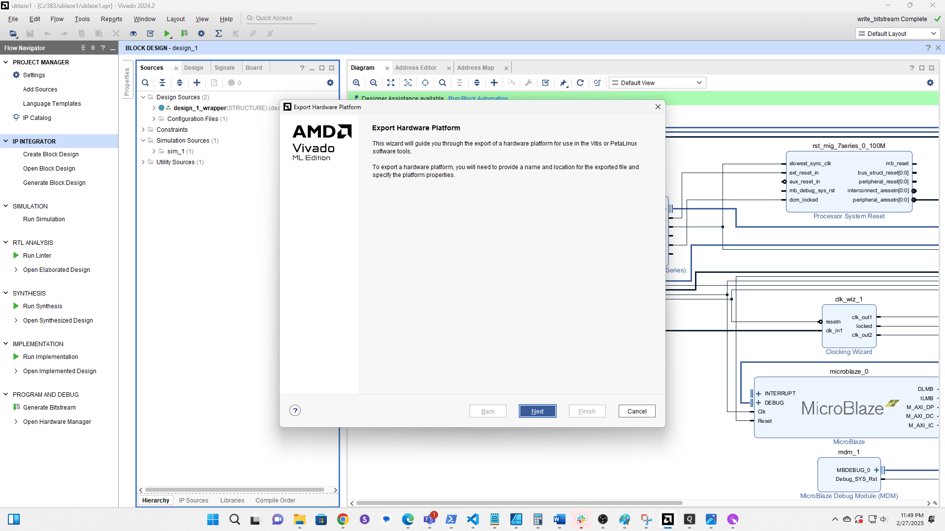
Select Include bitstream then click Next
Click here
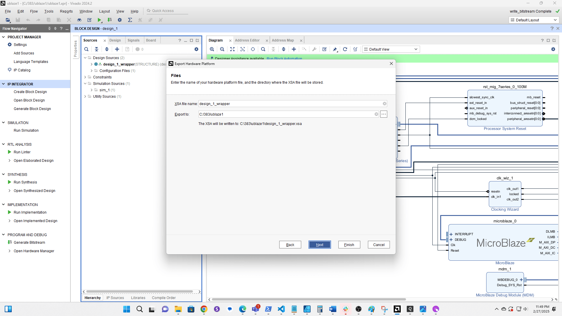
Click here